This thread has been locked.

If you have a related question, please click the "Ask a related question" button in the top right corner. The newly created question will be automatically linked to this question.

TPS62160 regulation issue

Other Parts Discussed in Thread: TPS62160, TPS62160EVM-627

Hello.

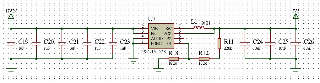
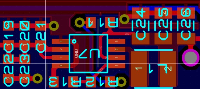
I am using the TPS62160 in the 8-pin MSOP package, to step down to 3.3V. The design uses a 2.2uH inductor and 30uF output capacitor.

However, it does not appears to regulate at all; the output voltage is approximately 3.3V at an input voltage of 6V, and increases with the input voltage until I believe it damages the FB and VOS inputs and shorts the SW output.

Any advise on possible cause and how to debug?

Thanking you in advance.


  • The first steps would be checking your schematic and layout versus the D/S recommendations and the EVM.

    If you just want a working board to test on, the EVM is available here: http://www.ti.com/tool/TPS62160EVM-627

  • I believed my schematic and layout is correct as per data sheet recommendation.

    I have the EVM; the main difference being my design uses the MSOP package while the EVM uses the WSON package.

    Any suggestion is much appreciated.

  • You can post your schematic and layout here, if you would like me to look at them.  Also, which inductor do you use?

    The MSOP and WSON packages have basically the same pinout so the layout should be essentially the same.  There should be no difference between the two.

  • The inductor used is the Bourns SRN3015-2R2M inductor 2.2uH 1.65A 72mR.

    Schematic and layout is as shown below.

    Thanks for your help thus far.

  • Thanks for posting these.  

    The device requires a 10uF input cap, so I recommend retesting with one of those or 2x 4.7uF instead of those 1uFs.

    As well, the inductor is right next to the FB pin.  It may be too close.  You can reduce your FB resistors by 100x (2.2k, 1k, 1k) to make that net more noise immune and see if the behavior improves.

  • Thanks for the feedback.

    Regarding the input capacitor, I have tested with a 22uF electrolytic and 5uF ceramic (the 5x 1uF), the ceramic being next to VIN. I gather this is sufficient?

    Short of a relayout, I will try reducing the FB resistors by 100x as advised, and report back. I have already tried  reducing by 10x with no joy.

    I assumed there is no issue with the said inductor?

  • Your inductor looks fine.

    Per the D/S, we need 10uF of ceramic Cin.  Electrolytics have far too much impedance to be used for power supplies switching in the MHz.

    A scope capture of Vin, Vout, SW, and the inductor current when the voltage is too high (say 4V) might tell us something.