This thread has been locked.

If you have a related question, please click the "Ask a related question" button in the top right corner. The newly created question will be automatically linked to this question.

Discharge Completion and Charge Completion ON in same time

Other Parts Discussed in Thread: BQ78PL116

Hi,

Chip(BQ78PL116)

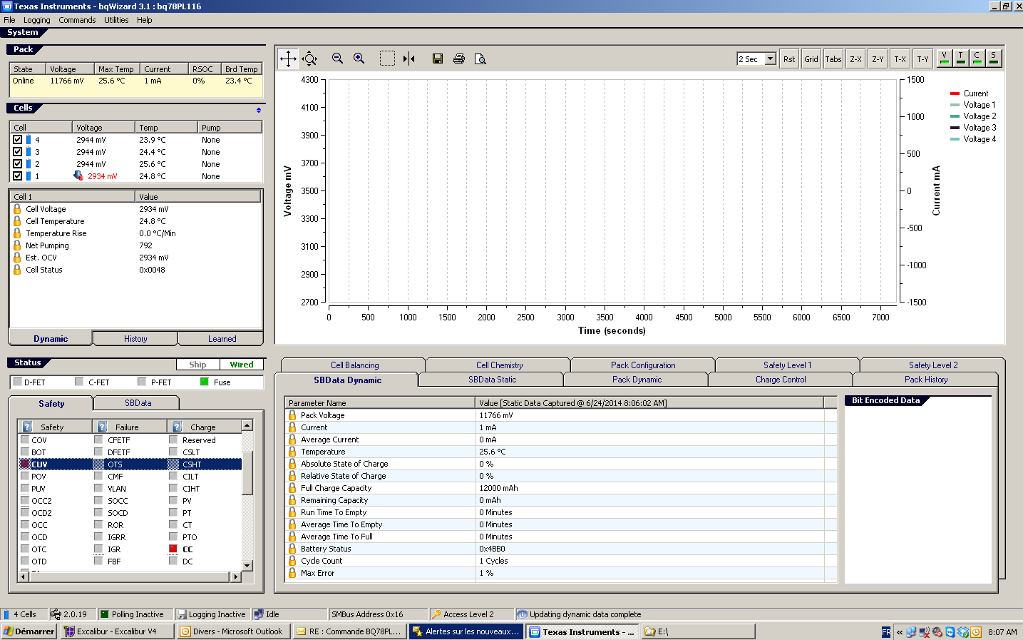
I received the batteries after sales service,  the flag of DC and DC flag is set to 1.

This occurs because the standby power consumption of the product is below the Transition to Idle Current.

The battery is fully charged (CC is set).
The standby mode of the product, slowly draining the battery (DC is set).

The RSOC is 0%.

The flag "Charge Completion" does not turn off and the battery is completely discharged.

The battery is unusable! It seems that this is a bug.

Did you do an update? 
Is what I omitted the configuration of a parameter?

Thanks

  • Julien

    I am out of the office and do not have access to my documents. You should try a relearn/initialize to see if this fixes the pack.

    Tom

  • Hi,

    This clears the problem.

    But the problem will return.

    He must miss an exit condition.

    Thank you to consult the technical document.

    Thanks

  • Hi,

    Can you answer the questions in my first post please?

    The battery is unusable! It seems that this is a bug.

    Did you do an update?

    Thanks

  • I verified that the CC flag will get cleared as the pack discharges, so the CC and DC flags should not get set at the same time. Can you provide a pack parameter dump for me to review? I may be able to find a parameter change that can help.

  • Hi, thank you for your reply.

    I have just come back from holiday. I apologize for being late.

    I apologize for my error : It is a old chip  -> BQ114.

    I am doing a test on the new chip BQ116, I would return to you with the new test, monday.

    Can you tell me the location where you found this information ?

    I find a similar information, but it concerns the flag FC and FD(Fully charge, Fully Discharge).

    The two flags have a correct operation, with 'Set SOC Threshold' and 'Clear SOC Threshold'.

    The attached file contains the configuration PPCSV. (Rename in. Txt)

    # bqWizard Version 3.2.0
    # Target = bq78PL114S12
    # Cells = 4
    # CapacityMode = Disabled
    # VScale x 1
    # IPScale x 1
    # Scaled values are identified by a division sign + scalar in the units column
    
    <SBData Static>,1,
    Manufacturer Name,,TECSUP OF 1202RZ : Add
    Device Name,,bq78PL114
    Device Chemistry,,LiFePO4
    Manufacturer Data,,0E4D616E20446174612020202020200000000000000000000000000000000000
    Serial Number,,6
    Manufacture Date,,4152
    Design Voltage,mV,12800
    At Rate,mAh/10mWh,0
    Battery Mode,,0x6001
    Remaining Time Alarm,Minutes,10
    Remaining Capacity Alarm,mAh/10mWh,2450
    
    <Charge Control>,3,
    Pre-Charge Temperature,Kelvin,270
    Pre-Charge Voltage,mV,2500
    Pre-Charge Recovery,mV,2600
    Pre-Charge Current,mA,400
    Charge Inhibit Temperature Low,Kelvin,268
    Charge Inhibit Temperature High,Kelvin,326
    Charge Inhibit  Recovery Temperature Low,Kelvin,271
    Charge Inhibit Recovery Temperature High,Kelvin,319
    Charge Suspend Temperature Low,Kelvin,272
    Charge Suspend Recovery Temperature Low,Kelvin,275
    Charge Suspend Temperature High,Kelvin,323
    Charge Suspend Recovery Temperature High,Kelvin,320
    Charge Completion Pack Voltage Qualifier,mV,14200
    Charge Completion Taper Current Qualifier,mA,120
    Charge Completion Time,Seconds RDTE,10
    Charge Completion FET Activation Time,Seconds RDTE,10
    Discharge Completion Pack Voltage Qualifier,mV,11600
    Discharge Completion Time,Seconds RDTE,4
    Discharge Completion FET Activation Time,Seconds RDTE,6
    Discharge Under Temperature,Kelvin,253
    Discharge Under Temperature Recovery,Kelvin,258
    Discharge Under Temperature Time,Seconds RDTE,2
    FC Set SOC Threshold,%,-1
    FC Clear SOC Threshold,%,-1
    FD Set SOC Threshold,%,-1
    FD Clear SOC Threshold,%,-1
    FD Set Voltage,mV,11600
    FD Clear Voltage,mV,11800
    FD Set Voltage Time,Seconds,0
    Transition to Idle Current,mA,50
    Transition to Idle Time,Seconds,30
    Transition to Discharge Current,mA,-15
    Transition to Charge Current,mA,75
    Cell Shutdown Voltage,mV,2500
    Design Capacity mAh,mAHrs,12000
    Design Capacity 10mWh,mWh / 10,3840
    TDA Set SOC Threshold,%,-1
    TDA Set Voltage Threshold,mV,11800
    TDA Set Voltage Time,Seconds,0
    TDA Clear SOC Threshold,%,-1
    TDA Clear Voltage,mV,10000
    TCA Set SOC Threshold,%,-1
    TCA Clear SOC Threshold,%,-1
    OCA Set Voltage,mV,14600
    OCA Activation Time,Seconds RDTE,2
    
    <Cell Balancing>,5,
    Minimum Cell Differential For Balancing,mV,10
    
    <Cell Chemistry>,6,
    Chemistry ID,,405
    FCC Learn Qualifier,%,30
    Cycle Fade,%,0.05
    Min OCV Slope,mV/% RSOC,2
    OCV Idle Qualifier,Minutes,30
    Stale FCC Timeout,Minutes,2880
    Default Charging Voltage,mV,14400
    Default Charging Current,mA,3360
    Capacity Algorithm,,0x0003
    User Rate,mA,2000
    Current Delta,mA,100
    
    <Pack Configuration>,7,
    Hardware Configuration,,0x0731
    Algorithm Enable,,0x000E
    System Control,,0x0000
    EPD Pump Time,Cycle Counts,120
    EPD Write Time,Cycle Counts,70
    Display Driver Frequency,Hz,30
    
    <Safety Level 1>,8,
    COV Threshold,mV,3650
    COV Recovery,mV,3600
    COV High Temperature Threshold,mV,3500
    COV High Temperature Adjust,Kelvin,323
    COV Time,Seconds,2
    CUV Threshold,mV,2900
    CUV Recovery,mV,3100
    CUV Time,Seconds,2
    POV Threshold,mV,14800
    POV Recovery,mV,14480
    POV Time,Seconds,6
    PUV Threshold,mV,11600
    PUV Recovery,mV,12400
    PUV Time,Seconds,1
    EUV Threshold,mV,2500
    EUV Time,Seconds,2
    EUV Recovery,mV,2700
    OC Charge Tier 1 Threshold,mA,8000
    OC Charge Tier 1 Recovery,Seconds,5
    OC Charge Tier 1 Time,Seconds,6
    OC Discharge Tier 1 Threshold,mA,-12000
    OC Discharge Tier 1 Recovery,Seconds,5
    OC Discharge Tier 1 Time,Seconds,8
    OC Charge Tier 2 Threshold,mA,9000
    OC Charge Tier 2 Recovery,Seconds,8
    OC Charge Tier 2 Time,Seconds,6
    OC Discharge Tier 2 Threshold,mA,-13000
    OC Discharge Tier 2 Recovery,Seconds,5
    OC Discharge Tier 2 Time,Seconds,6
    OC Max Attempts,,20
    Hardware OC Charge Threshold,,0
    Hardware OC Charge Recovery,Seconds,10
    Hardware OC Charge Time,,127
    Hardware OC Discharge Threshold,,255
    Hardware OC Discharge Recovery,Seconds,10
    Hardware OC Discharge Time,,127
    HOC Max Attempts,,20
    Hardware Short Circuit Threshold,,63
    Hardware Short Circuit Recovery,Seconds,10
    Hardware Short Circuit Time,,31
    HSC Max Attempts,,20
    OT Charge Threshold,Kelvin,325
    OT Charge Recovery,Kelvin,322
    OT Charge Time,Seconds RDTE,2
    OT Discharge Threshold,Kelvin,336
    OT Discharge Recovery,Kelvin,333
    OT Discharge Time,Seconds RDTE,2
    Board Over Temperature,Kelvin,358
    Board Over Temperature Recovery,Kelvin,333
    Board Over Temperature Time,Seconds RDTE,2
    Hardware LP Discharge Threshold,,255
    Hardware LP Discharge Duration,,127
    Hardware LP Charge Threshold,,224
    Hardware LP Charge Duration,,127
    Host Watchdog Timeout,Seconds RDTE,0
    
    <Safety Level 2>,9,
    SOV Threshold,mV,3800
    SOV Time,Seconds RDTE,8
    Cell Imbalance Current,mA,50
    Cell Imbalance Fail Voltage,mV,500
    Cell Imbalance Time,Seconds,180
    Cell Imbalance SOC Inhibit Threshold,%,30
    SOC Charge Threshold,mA,10000
    SOC Charge Time,Seconds RDTE,2
    SOC Discharge Threshold,mA,-17000
    SOC Discharge Time,Seconds RDTE,2
    SOT Charge Threshold,Kelvin,343
    SOT Charge Time,Seconds RDTE,2
    SOT Discharge Threshold,Kelvin,343
    SOT Discharge Time,Seconds RDTE,2
    Open Temperature Sensor Threshold,Kelvin,233
    Open Temperature Sensor Time,Seconds RDTE,2
    FET Fail Time,Seconds RDTE,2
    Fuse Fail Limit,mA,40
    Fuse Fail Time,Seconds RDTE,2
    VLAN Fail Time,Seconds RDTE,2
    Current Measurement Fail Time,Seconds RDTE,10
    Pre-Charge Voltage Timeout,Seconds RDTE,1800
    Charge Duration Timeout,Seconds RDTE,21600
    IGR Limit,,400
    IGR Fail Count,,0
    IGR Ratio Limit,,200
    IGR Ratio Fail Count,,0
    Rate Limit Threshold,,200
    Rate Limit Activation Count,,100


    Thanks

  • The TRM does not state that the CC flag will clear if the pack is discharged with the current set below the discharge current threshold. I had verified it on the bench. I reviewed your .ppcsv file and some of flag control parameters are setup differently from the ones that I was using. I will test your parameters on the bench setup.

  • Hi,

    I just finished the test with a BQ78PL116.

    The transition current discharge is set to '-120mA' to go faster.

    The discharge current was him '-100mA.

    The DC flag (Discharge completion) is this not on, but the result is the same.

    CUV (under Cell voltage) is set to 1. 

    The battery is unusable.

  • Julien,

    I was able to reproduce the case where CC did not clear when the discharge current was below the Discharge Current Threshold. You have the FC Clear SOC Threshold parameter set to -1. Set it to a percentage (e.g. 95%) and the CC flag should clear when the SOC reaches 94%.

    Tom

  • Hi,

    I write because I have already tried ...

    See my previous post, citation :

    <<< I find a similar information, but it concerns the flag FC and FD(Fully charge, Fully Discharge)."

    The two flags have a correct operation, with 'Set SOC Threshold' and 'Clear SOC Threshold'. >>>


    This does not work for CC flag.


    Thanks

  • Julien,

    The FC Clear SOC Threshold parameter setting is the only way that I could reproduce the issue on the bench. I will work with your pack, if you want to send one to TI.

    Regards

    Tom