This thread has been locked.

If you have a related question, please click the "Ask a related question" button in the top right corner. The newly created question will be automatically linked to this question.

BQ27421-G1

Other Parts Discussed in Thread: BQ27421-G1

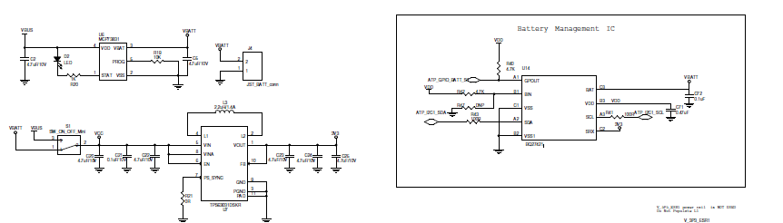
The data sheet for the BQ27421-G1 part states " Recommend using a pull-up resistor >1MΩ (1.8 MΩ typical) to VCC for reduced power consumption." for the BIN pin. (datasheet May 2013, page 3)

This part has no VCC pin. Is this a typo and should it be VDD?

Tom

  • Hello Tom,

    A second source of information that can sometimes clear up confusion that you might have from the datasheet is the user guide for the EVM.

    The EVM schematic shows that there is a pull-up from BIN to VDD just like you are curious about.

    Also for future reference there are two forums for the battery related devices: chargers and gauges and this would fall under the gauge forum so for any further questions please post in the following link for the best support.

    http://e2e.ti.com/support/power_management/battery_management/f/180.aspx

  • Hi Ryan,

    I have used BQ27421 IC in one of my project. I have attached the BQ27421 Schematic section and USB rechargeable section and 3.3V LDO section. My problem is when i try to measure the Voltage across C24 i.e, for the net "3V3" i'm getting 4V instead of 3.3V. When i removed BQ27421 IC from the Board i'm getting 3.3V across the NET "3V3". Can you please help me to figure out why i'm getting 4V in the presence of BQ27421 IC and 3.3V in the absence of BQ27421 IC.

  • Hello Lokesh,

    Thank you for your question.

    Can you attach some more zoomed in versions of these schematics? I can not read any of the part numbers or component values.

    I have a few questions:

    -Where are the following NETs coming from and what voltage can we expect on them?

    VBUS

    VBATT

    VDD

    VCC

    I can not think of anything off hand for why the voltage would change with the presence of the bq27421. When the bq27421 is depopulated what is the state of the S1 component? Is it sourcing the converter with VBUS or VBATT? 

    The other question I have is what part is that converter? If it is a full 4-switch buck-boost then it should be more than capable of producing the 3.3V from a battery voltage. Looking at how the inductor is configured that would be my guess for the topology. However it is just a boost converter then we may be dealing with an issure of pass through where the device is not able to regulate down to 3.3V from a supplied battery voltage of 4V.

    When you see 4V on C24 what is the voltage of the battery?

    I look forward to hearing back from you so that we can get to the bottom of this issue quickly.