This thread has been locked.

If you have a related question, please click the "Ask a related question" button in the top right corner. The newly created question will be automatically linked to this question.

TLC59282 Daisy Chain Connection Problem

Other Parts Discussed in Thread: TLC59282

We try to use TLC59282 with daisy chain connection. Our spi signal look like this image ;

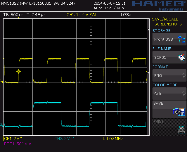
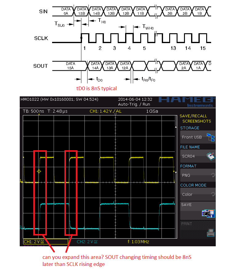
yellow is SCLK and blue ise SIN for TLC59282. But TLC59282's SOUT signal look like this ;

The sout work like falling edge trigered. But device datasheet show this signals rising edge trigered.


Device connected a 8 bit CPU development board and any other device connected to SPI Bus.


Why SOUT working like this? Where is the problem ?

  • Hello,

    This SOUT waveform is ok. TLC59282 detect SIN at the rising edge of SCLK, and store this data in LSB of shifter register. At the same time, the common shifter register is shifted 1bit toward MSB. To make sure the next cascaded IC(denote as the 2nd IC here) can sample the SOUT of 1st IC correctly, the SOUT keep unchanged for 8nS (tD0 in datasheet) after receiving SCLK rising edge. After this tD0 period passed, the MSB-1 of common shifter register will be shifted into MSB, and SOUT will change to this new level.

    Since the minimum needed hold time for SIN is 4nS (Th0 in datasheet),  this 8nS tD0 is OK for correct data transmittion as long as the SCLK for each IC is same.

    Regards

    Mike