This thread has been locked.

If you have a related question, please click the "Ask a related question" button in the top right corner. The newly created question will be automatically linked to this question.

bq24260 - Charge Time Optimizer

Other Parts Discussed in Thread: BQ24192, BQ24296, BQ24040

I'm considering the bq24260 for a project and the Charge Time Optimizer feature seems great. 

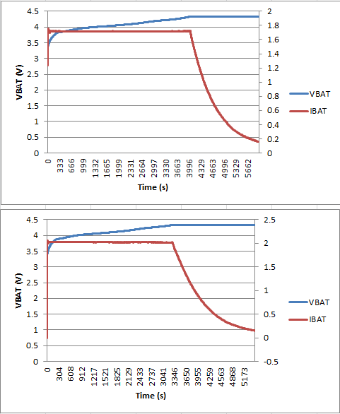
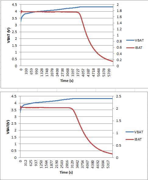
With regard to the CC/CV knee transition, can you explain what is done done differently in the bq24260 versus the bq24192, which we are currently using?

The written explanation of charge method in the datasheets is basically the same - the charger is in CC mode until the regulation voltage is reached, then changes to CV mode. 

Thanks,

  • Hello Bryan,

    While I have not obtained any charge cycle data for the BQ24192 I have worked with the BQ24296 which is a sister part and I have worked with the BQ24260.

    The charge time optimizer that is used in the 260 help to sharpen the transition from CC to CV. While the testing I performed with the 296 showed it to perform admirably when it is compared with the 260 the later transfers a little bit more power before it switches control schemes.

    Here are two sets of data that I took for each device with the same battery. You can notice the sharper transition when using the 260 and that reduction in charge time.

    BQ24260

    BQ24296:

  • Ryan,

    Thanks for the quick response and graphs, they look great. Still looking for more detail though...

    Since the CC/CV transition is the max power point during charge, I always assumed the rounded knee was due to a thermal limitation of the IC, perhaps the FET Rdson increasing or a voltage reference drifting with temperature.

    So I'm curious which of these mechanisms was compensated for to get the sharp CTO knee.

  • Our 1st generation chargers use a simple OR'ing method where all of the error amplifiers for the various feedback loops (CC,CV,ILIM, etc.) alter the FB point of the power stage amplifier in the exact same manner and same priority.  The block diagram of one of the older parts, like bq24040, shows this with the error amplifiers pulling down the same node.  This can result in loop interference during the transition between loops, which, for the transition between CC and CV, leads to a soft knee in the charge current curve.  For the 2nd generation chargers, of which 260 is a member, the current loops are grouped together and feed into one amplifier while the voltage loop has its own amplifier.  These two amplifiers independently set the duty cycle for the switching power stage.  An OR gate selects the longer of the two individually computed duty cycles.  This eliminates loop interfence between current and voltage regulation and allows for individual compensation for the voltage and current loops.  So, not only will the CC to CV knee be sharper, the transient response of the voltage loop is much improved. 

  • Jeff, thanks so much for the detailed explanation. It's clear now.