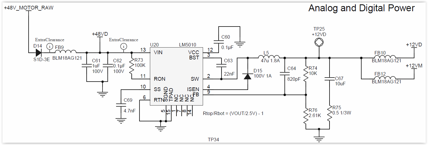
I am working on a LM5010 design taken primarily from Webbench and I am getting odd behaviour:
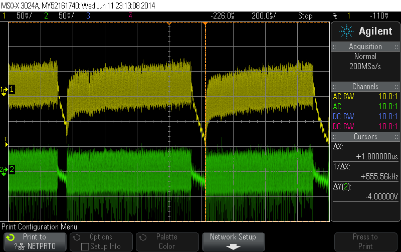
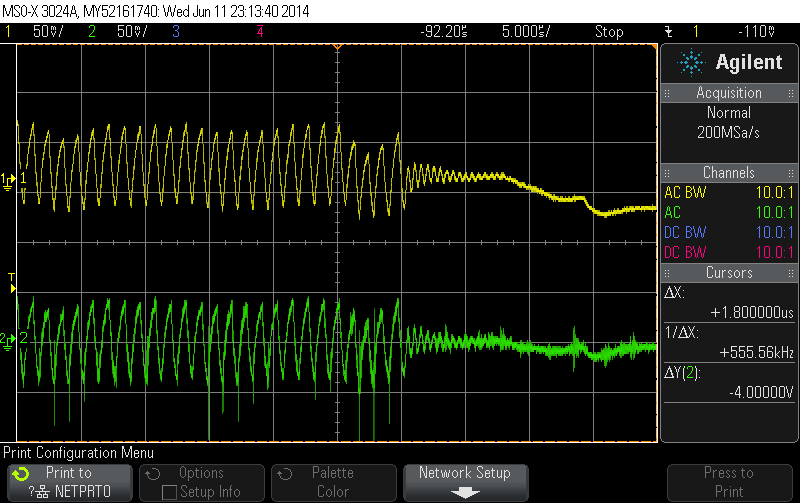
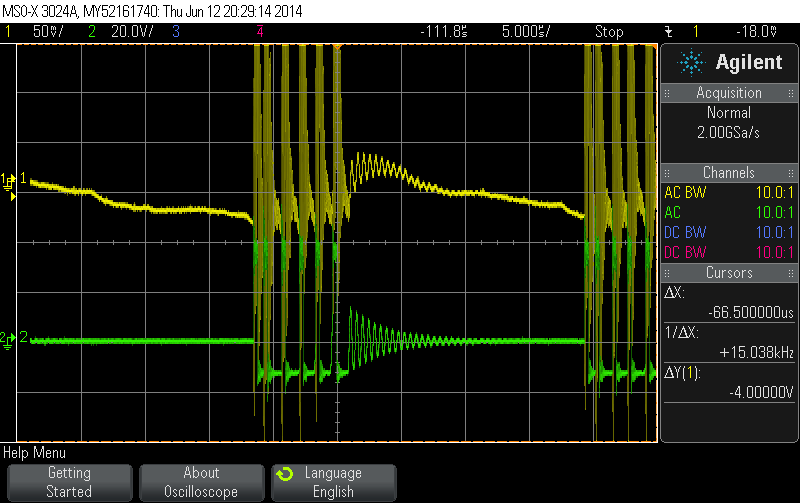
Yellow: Vout AC coupled
Green: Feedback pin AC coupled
The desired output is 12V and the behaviour changes depending on the input voltage:
@15V: around 10Vout@700kHz (toff ~270ns) - no issues
@20V: around 12.3Vout@1MHz (toff ~270ns) - no issues
@25V: around 12.3Vout@1MHz (toff ~350ns) - odd "stopping" behaviour shows up every millisecond or so and lasts for ~100 us
@40V: around 12.3Vout@1MHz (toff ~ 700ns) - stopping behaviour happens around every 200-300us.
A few things I have been investigating: I originally started with a non-shottky diode and based upon info from the forums, I switched to a fast schottky, though maybe not optimal (STMICRO STPS3H100U).
The main things that would seem to cause this behavour in my mind are:
-tripping the 2.9V cuttoff (but the feedback voltage barely changes...)
-Overcurrent? There is only around 100mA of draw on the circuit.
-Basic instability?
-outside of the shown circuit there is over 20uF of ceramic capacitance through the shown ferrite beads. The beads may poorly combine with the caps to create a bad harmonic frequency? Maybe the beads don't provide enough DC resistance to keep the caps from oscillating the output...
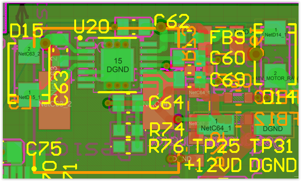
-The inductor is up against the power plane (12V) rather than a ground plane. Could this cause issues?
-Maybe my layout itself is bad - I have a hard time assessing this completely.
Thanks for your help-