This thread has been locked.

If you have a related question, please click the "Ask a related question" button in the top right corner. The newly created question will be automatically linked to this question.

LM25011 Annoying Audible Noise

Other Parts Discussed in Thread: LM25011

Hi,

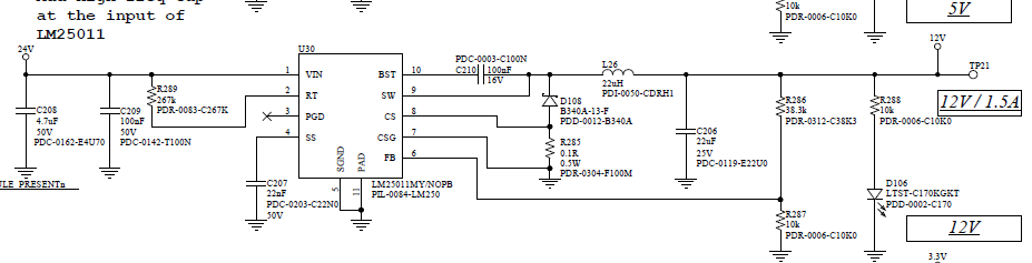
We designed 3x DC-DCs with the LM25011. One of the 3 DC-DC is doing 24V to 12V and has almost no load at boot-up. The DC-DC goes out of the discontinuous mode only when the user start a motor or do something with the machine.

The problem is this DC-DC is generating a lot of audible noise in probably 15-17kHz when in discontinuous mode. Except adding more load at the output, what can I do to decrease this noise?

Thanks,

Denis

  • Can you share the circuit?

    Playing with inductor, frequency, ripple, and/or COUT can change the noise.

  • Hi,

    Sorry for the delay. I continued lately the investigation on this circuit... We worked with small load to avoid the audible noise... but now I need to correct this.

    Looking at the 12VDC output, the DC-DC is definitely causing a lot of VOLTAGE noise on the 24VDC!!!! I shorted the SS cap to stop the DC-DC and the noise on the 24VDC decrease from 230mV to 80mV. So I have two "types" of noise now: one audible, another in term of volts!!!! The layout itself is not perfect (we knew it, but time / space constraints forced us to release the PCB with this not perfect current loops).

    We have 1000uF electro on 24VDC, + the 4.7uF ceramic at the input. I think we should add more ceramic at the input! Also, I will try to increase output cap (also ceramic), since the output voltage noise is about 104mV... This is not RIPPLE voltage, but SW noise. This is our circuit: 

    I can probably deal with the SW noise myself... at worse, BOM change + modifying the layout will correct the voltage noise.... but what do you propose for the audible noise? Do you think layout change can affect the audible noise?

    Thanks,

    Denis

    P.S.: Our output current can change from 0A to about 1A.

  • Just to confirm. You are seeing this audible noise only at no load. Is that correct?

    I don't see any ripple circuit on the output. It may cause oscillation and noise.

  • Hi Vijay,

    Yes, the audible noise is only at no load or light load... We are using the LM25011 (not the LM25011A), so I assumed that the external ripple circuit is not necessary... from the spec:

    "Ripple voltage, which is required at the input of the regulation comparator for proper output regulation, is generated internally in the LM25011, and externally when the LM25011A is used"

    From what I understand, the ripple voltage at Cout is necessary for LM25011A only... For the LM25011, the ripple is generated when IL is decreasing at Cs pin.

    Also, according to the specification at page 12:

    "The LM25011 requires about 25mVp-p of ripple voltage at the CS pin"... 

    I measured about 25mV of ripple at CS pin with a very short ground (at no load)! I may need more margin on this! The point is, the design example at page 16, we can also read:

    "As mentioned in the Ripple Requirements section, a minimum of 15 mVp-p voltage ripple is required across the RS sense resistor during the off-time to ensure the regulation circuit operates properly"

    I reviewed my design spreadsheet and I designed for 30mV of ripple voltage.

    What is the minimum ripple voltage at the CS pin for the LM25011? 15mVpp or 25mVpp?

    What should be a safe design margin for this ripple voltage?

    Do I really need an external ripple circuit like the series resistor on Cout for the LM25011M?

    Many thanks for your help,

    Denis

  • Hi Denis,

    At light load the part goes in DCM (discon cond mode). In this mode the inductor current can drop to zero. The part switching then depends only on VOUT.

    There is no definite way to get rid of the burst mode behavior in DCM. Increasing VOUT/FB ripple has helped in the past in reducing noise.

    Thanks and regards,