Blue is Vin AC, Yellow is Iin AC. 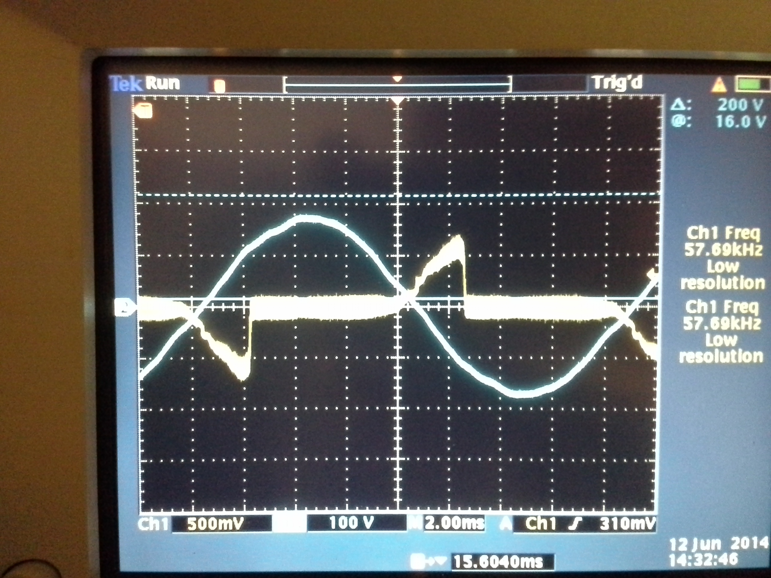
Everything appears fine for the first quarter of half the cycle, then the current goes to zero.
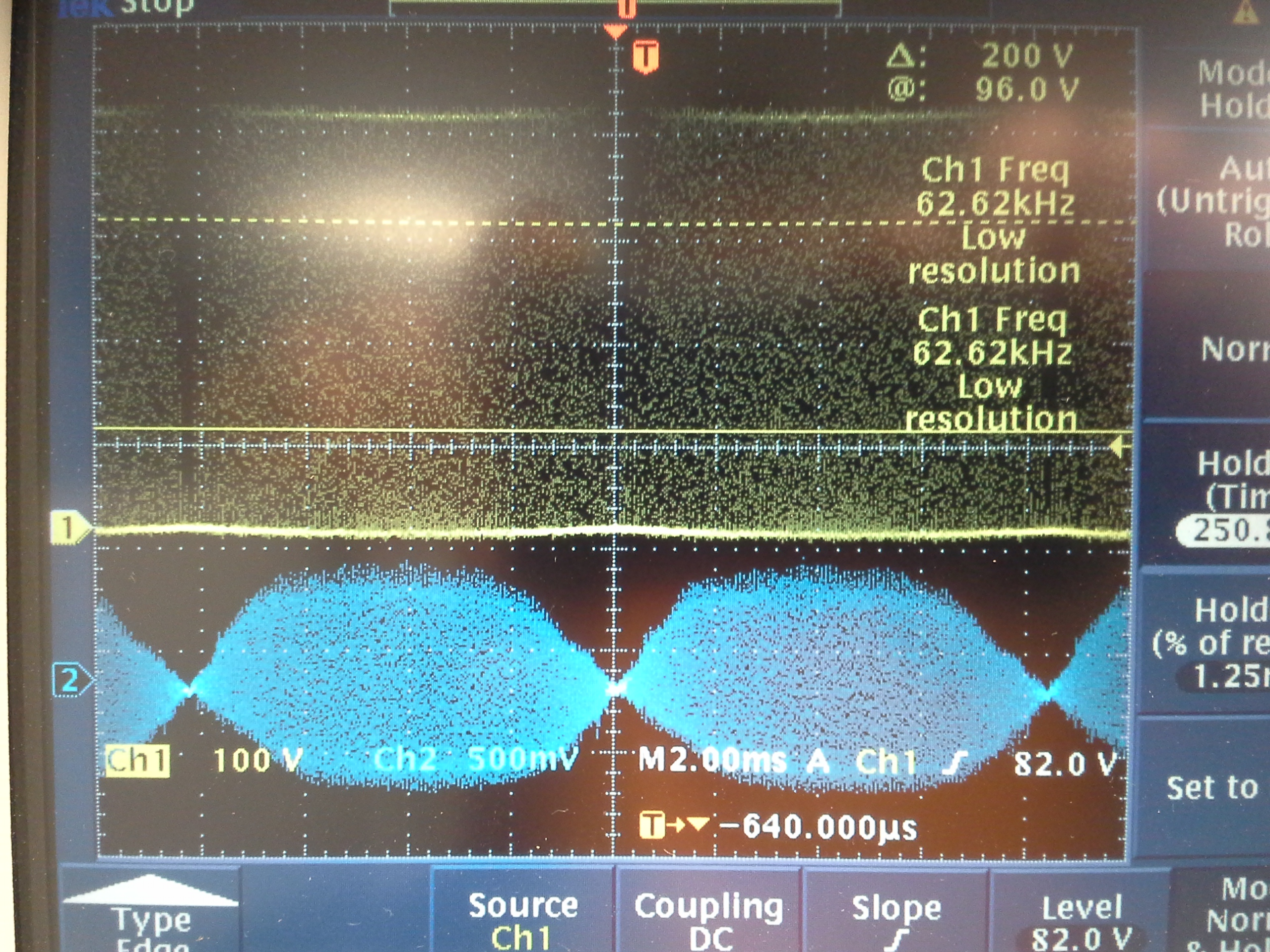
Vin is 110-120 VAC. Output is around 380 VDC @ 50 Watt. The peaks get higher and shorter in duration as load is increased.
Values from the excel calculator ( I had the max and min RMS input set at 210-220 VAC, doesn't seem to effect the waveform running at 110 or 220 ) @ 65 KHz :
Rfreq: 33K Ohm
Cin: 0.47 uF
Lboost: 1.4 mH
Rsense: .07 Ohm
Risense: 220 Ohm
Cisense: 1500 pF
Cout: 600 uF
Cvsense: 820 pF
CIcomp: 4700 pF
Cvcomp: 10uF
Cvcomp_p: 0.47 uF
Rvcomp: 20K Ohm
Schematic is the same as the EVM except for a different inductor, Mosfet and Shottky
I've tried gapped ferrite E cores and a sendust 75u torroid for the boost inductor with similar results.
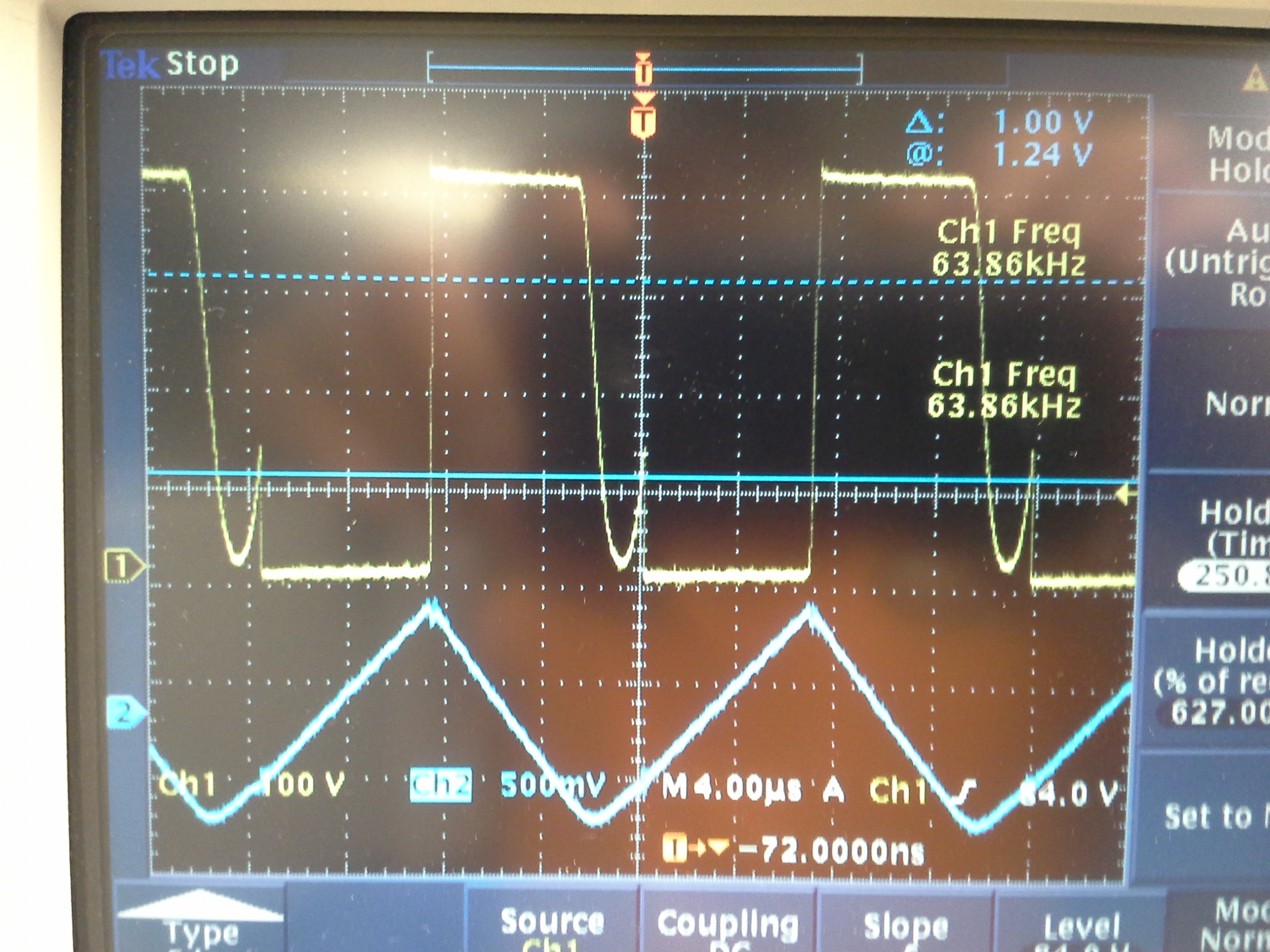
What are the waveforms on the Icomp and Isense supposed to look like? I don't see those shown anywhere in the datasheets.
Oddly, if I use an isolated 70-80 Vrms, 500-600 Hz AC supply, the input current becomes sinusoidal and in phase with the input voltage . Not sure if this is related to the input voltage being lower, frequency higher or the isolation.
Thanks