


Hi everyone and John Tucker,
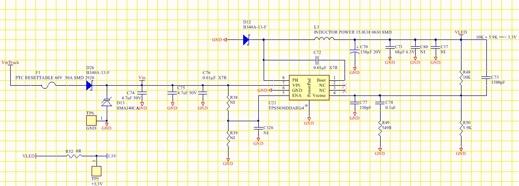
For some reasons, in my newest PSU design, I read a lot of ripple at the output. At first, I thought it could be the ceramic capacitor at the output. We added the calibration circuit.
We used all the recommended components. Sumida inductor, X5R capacitors, followed the calculations, etc
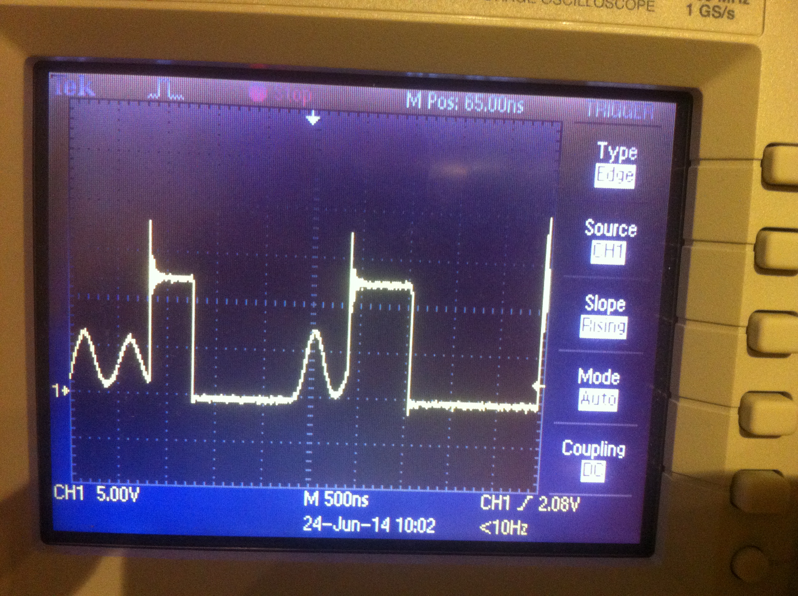
You will see below that even without load conditions, the ripple is really high.
We reused the layout from another board, we checked and measured on this previous board, and everything is fine. maybe there is a little detail on the layout.
Any advice would help.
Thanks in advance
Sebastian
here is a screenshot of the top layer :

here is the bottom view :

Here is a few probing screenshot of the circuit :

here is two screenshot with 2 timebase:


Finally, here are BOOT and PH pins at full load 1.2A 3.3V out
PH pin first
BOOT pin now
:


