This thread has been locked.

If you have a related question, please click the "Ask a related question" button in the top right corner. The newly created question will be automatically linked to this question.

TPS62140A switching spikes in VIN and VOUT

Other Parts Discussed in Thread: TPS62140A

Hello,

For a project we use the TPS62140a to convert a 12V DC input to 5V DC output. the load will draw a maximum current of 1.25A. The problem i'm facing is that large spikes appear in the 12V power rail as wel as in the vout. It looks like they are caused by the switching pulses. The graphs in the datasheet shows clean output signals, but we are not getting that. What can be the issue that causes these spikes and how can we loose those spikes?

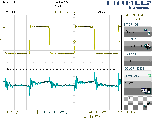
The picture below shows the signal on the SW pin in green and the 5V output after the coil in blue. The load  draws 1A. The signals are measured with the scope set to ac

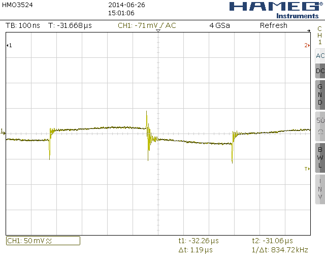
the following picture shows the 12V input rail and the 5v output rail. The load draws 1A. The scope is again set to ac.

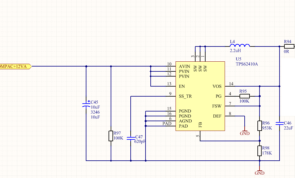
The next picture shows the schematic i've used.

and the final picture shows the lay-out on the board

With kind regards

Gort

  • I don't think that the capacitor C45 you are using is suitable for such a DCDC converter design. On the layout it looks like an aluminium electrolytic type. You need something more suitable for the high frequencies (switching and noise), like ceramic capacitors. They will be mechanically smaller and can be placed closer to the input pins which should improve the filtering performance significantly.

  • Yes, I agree with Juergen.

    As well, you should measure these types of signals with a low inductance probe to not pick up so much noise.  This is shown here: http://www.ti.com/lit/an/slva494a/slva494a.pdf

  • Thanks for your quick reactions. I have changed the input capacitor by an ceramic one and increased it from 10uf to 20 (2 times 10uf). Only at this moment I can only test it on the pcb circuit as shown in the previous post. I also changed the output capacitor (it was a 22uf ceramic cap) to twice a 10uf ceramic cap. Finaly I changed the way I measured the signals. I only performed one measurement at the time, and I've used the low inducatance probe. The measurement results are improved compared to the previous measurements, and I notice that the way of measuring gives the most deviation in spikes.


    the next picture is the 12V power rail measured over the input capacitor. The load takes 1 amp on 5V.

    The next picture shows the output voltage measured over the output capacitor.

    I read that the spikes can be eliminated by looking at the resonance frequency of the spikes and select a capacitor with a self resonance frequency of that ringing frequency. So I will try that next.

    With kind regards,
    Gort.