This thread has been locked.

If you have a related question, please click the "Ask a related question" button in the top right corner. The newly created question will be automatically linked to this question.

BQ24650evm-639 charge current

Other Parts Discussed in Thread: BQ24650EVM-639, BQ24650

Hello~

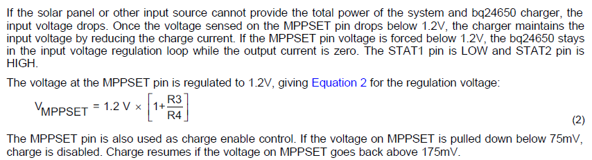
I have a solar module(18V, Short Circuit current 4A)

I want to charge LiPo 11.1V battery.

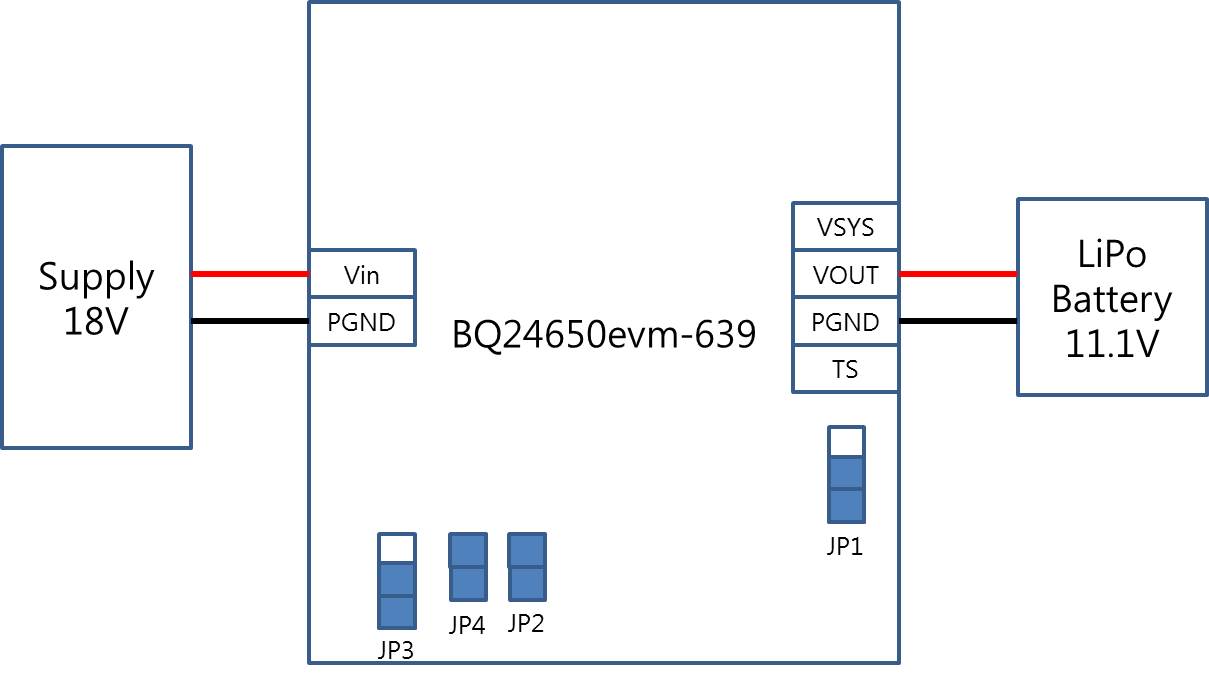
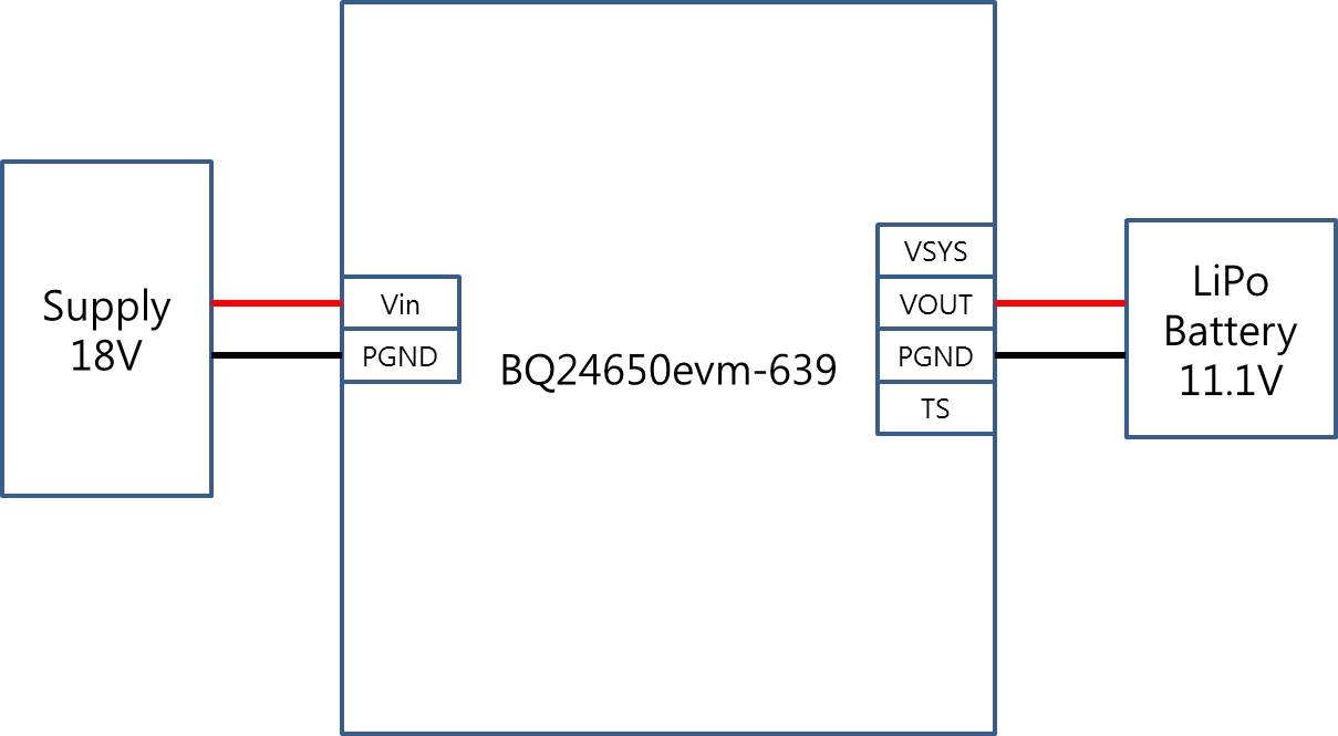
So, I have connected for test as follow.


                [Supply 18V] - [BQ24650evm-639] - [LiPo 11.1V battery]

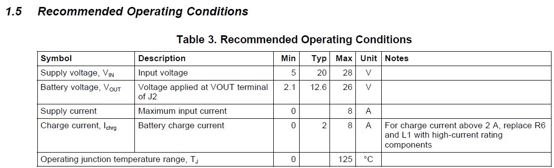
We  obtained 12.6V and almost 0A..

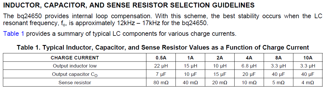
We can't obtain 2A..

How to obtain 2A?

And We want to increase 4A about charge current.

How to change 4A? only change R6???

  • Hello Hyeon-Bo,

    To help problem solve what you are not seeing any charging can you check the Jumper positions and list them in your next post. Also what is the state indicated by the STAT pins?

    The answer to the second question for how to increase the current capacity of the EVM you will need to follow the recommendations from the User Guide and using the Datasheet to calculate the new component sizes.

  • Hellow Ryan,

    Thank you for your answer!!!

    I set Jumper position as follow.

    JP1(TS-Internal), JP2(On), JP3(TERM EN-DIS) JP4(On)

    When I supply input voltage (18V), D4(STAT1) led is on and D5(STAT2) led is off.

    This setting is wrong???

    And I want to charge current 4A.

    So I had calculate R6, but I don't know how to calculate L6.

    Would you mind showing me how to calculate L6???

    P.S Test in datasheet is something like setting??? Or just test???

  • Hello Hyeon-Bo,

    First I will talk about the inductor selection. The datasheet for the BW24650 discusses the output filter components on Pg. 17 here is a screen shot of them below. Two key characteristics  that the inductor must have is at least the recommended inductance and that it is rated to handle the expected continuous charging current with some head room.

    I do not see anything in your jumper configurations that would immediately suggest it should not be charging. So you are seeing 12.6V on the output?

    The datasheet provides a listing of criteria on Pg. 14 that must exist for charging to occur. Have you run through testing these values?

  • Thank you Ryan !


    Inductor problem is solved for your help!

    But, Unfortunately charge current problem is not solved.

    I think, You and I have different datasheet.

    I have a bq24650evm-639 datasheet. Datasheet link is...


    http://www.ti.com/tool/BQ24650EVM-639?keyMatch=bq24650evm-639&tisearch=Search-EN


  • Hello Hyeon-Bo,

    There are is also a datasheet for the BQ24650 in addition to the BQ24650EVM User Guide.

    See here for the datasheet I have been referencing.

    http://www.ti.com/lit/pdf/slusa75

    Have you had a chance to review and test the cases in which charging is disabled as detailed in my previous post?

  • Hello Ryan!!

    I obtained charge current 2A!!


    My purpose is when I supply input voltage 18V, I want to obtain charge current 2A.

    But when I supply 20V,

    that time I can obtain charge current 2A.


    Can you tell me Why happen this situation?


    p.s My solar module generate 18V, Short Circuit Current 5.59A

  • Hello Hyeon-Bo,

    The fact that it is working at one voltage input and not the other I am thinking it might be related to the MPPT on the input. What is the voltage at the input to the EVM when you achieve charging?

    It is possible that the voltage sensed on the input of the  chip is low enough that the MPPT algorithm places the chip in a non-charging state.

    Try measuring the voltage on the input and at the MPPSET test point.

  • Hello Ryan,


    I want to charge when I supply input voltage 18V.

    Because, My solar module generate 17~19V.

     And I conducted 2 test.

    First, I connect Power Supply for input voltage.

    Second, I connect my solar module.


    I obtained same result.

    When I supply below 18V, It doesn't charge.

    But, above 18V, start to charge.


    And When I supply 18V, MPPSET pin voltage  is about 1.1V.

    When I supply About 20V, MPPSET pin voltage is 1.2V.


    STAT1 LED is always on when I supply above 5V inputvoltage.


    So I think, above 18V is operation voltage for charge.

    What do you think of this situation??