This thread has been locked.

If you have a related question, please click the "Ask a related question" button in the top right corner. The newly created question will be automatically linked to this question.

LM3478-Boost

Hi all,

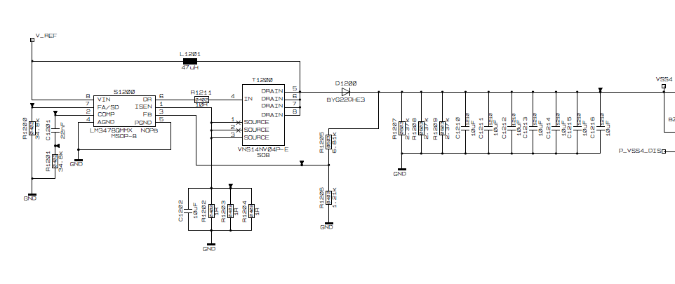
I have designed a step up based LM3478. My requirements are: 

Vin min: 6.3V

Vin max: 6.7V

Vout = 8.5V

Iout max = 150mA

Because of components availability and limited PCB space I have followings restrictions:

- possible boost inductor values: 10uH / 650mA, 22uH / 450mA or 47uH / 350mA

- Output capacitor value: max. 7x10uF (ceramic cap)

These values deviate from recommended part values by WEBENCH.

If I try to change the values in the WEBENCH then I get  the warning that changes may cause instability in my design.

My question is now,

how does look the compensation network if I use the above mentioned values for the boost inductor and output capacitor?

Can anybody help me?

Attached is the Webench design report.

thanks.

Erdal Guel

  • Hi Erdal,

    In WEBENCH you can simulate the stability of the loop by running the Bode plot in on the simulation page. From here you can play with compensation values to test your stability.

    For your requirements, since you Vin and Vout are close you min Dutycycle is going to limit the frequency you can use.

    I did a WEBENCH design at about 390KHz using 47uH and 70uF and good compensation looked like 3Kohms for Rcomp, 50nF for Ccomp and 1.5nF for Ccomp2. Try that out.

    Best regards,
    Tommy

  • Hi Tommy,

    thank you for your quick respond.

    Unfortunately we haven´t f designed Ccomp2 in our layout.

    I want also to change the value of the current limit because the preferred inductor (47uH) has a rated current of 350mA @25 °C and only 280mA @105°C. We already have two failures with damaged inductor. In both cases was load current <20mA.

    I can select the new value of Rsense with the formula Rsense= (Vsense - (DxVSL)) / ISW(PEAK)

    Does the change of Rsense have influence on the compensation network?

    I attached our currently design, which has been designed by my forerunner.

    Best regards

    Erdal

  • Hi Erdal,

    Not having the Ccomp2 in this case should be alright since we are keeping the system pretty slow.

    Changing the Rsens changes the overall gain of the system, but in this case you probably aren't changing it too much (are you bumping up to like 375 mOhms?) so it wont affect the compensation too much.

    BTW I think I might have been a little conservative with the 3kOhms. For a better transient I might bump that up to 8K-10K. This will give a little bit of a higher crossover for better transients while still maintaining a good phase margin for stability and keeping a good gain margin so its still ok that you don't have Ccomp2.

    Best regards,
    Tommy

  • Hi Tommy,

    I calculate Rsense to 0.619 Ohm with RSEN = (VSENSE - (D * VSENSE * VSL ratio)) / ISWLIMIT

    where Vsense=0.19 V, D=0.293, Vsl ratio=0.3 and ISW limit=280mA

    What is the exactly relationship between Vsense and inductor current?

    If you look at the attached picture the measured Vsense does not correspond to the specification of 123mV - 190mV. (Measured with Rsense=1 Ohm and 10mA load)

    Does the capacitor C1202 (10uF) have influence on the current limit value. Should we decrease the value?

    Which part did you mean with 3kOhms? Rcomp?

    What would you change if you look at our design in order to reduce the inductor current (<280 mA) ?

    Thank you for your support

    Best regards

    Erdal

  • Hi Erdal,

    That is a bigger change in Rsense than I expected, you may want play with the compensation a bit after that. But at 10k-15k for Rcomp you should still be Ok.

    Vsense is a threshold voltage for reaching current limit. So if inductor current times rsense (with the change in ramp voltage and dutycycle taken into account) hits Vsense, the switching cycle will end even if its not enough to regulate your load.
    At currents lower than max load you would not necessarily expect to see Vsense at the Isense pin.

    Your cap C1202 is usually used with a 100Ohm resistor (unless more slope comp is needed) as a filter for the Isense pin to get rid of high frequency noise from the turn on/off of the FET.
    Its usually on the order of 10nF not 10uF. 10uF would very much slow the voltage being seen at Isense allowing your part to go over current limit.
    From your pic it seems like it is, as at an inductor current of 237mA and a 1Ohm Sense resistor you should see Isense around 237mV not 88mV. It should also go to zero when the FET turns off.

    Yes I meant Rcomp

    Your inductor current should actually be close to 280mA I think (assuming you fix the Current sensing problem):
    At 85% effeciency (assumption) you average inductor current would be 8.5*.15/(6.3*.85) = .24A
    At 26% Dutycycle and 385KHz Inductor swing should be 6.3*.26/(47u*385KHz) = .09A
    So peak inductor should be around .24+.09/2 = .285A

    To decrease this you would need to either increase your frequency or your inductance. Frequency is kind of stuck because of the min on-time of the part.

  • Hi Tommy,

    thank you a lot.

    Best regards

    Erdal