This thread has been locked.

If you have a related question, please click the "Ask a related question" button in the top right corner. The newly created question will be automatically linked to this question.

USB single cell charge on two cell system

Other Parts Discussed in Thread: TPS61040, TPS61041, TPS61045, LMR62014

Hi,

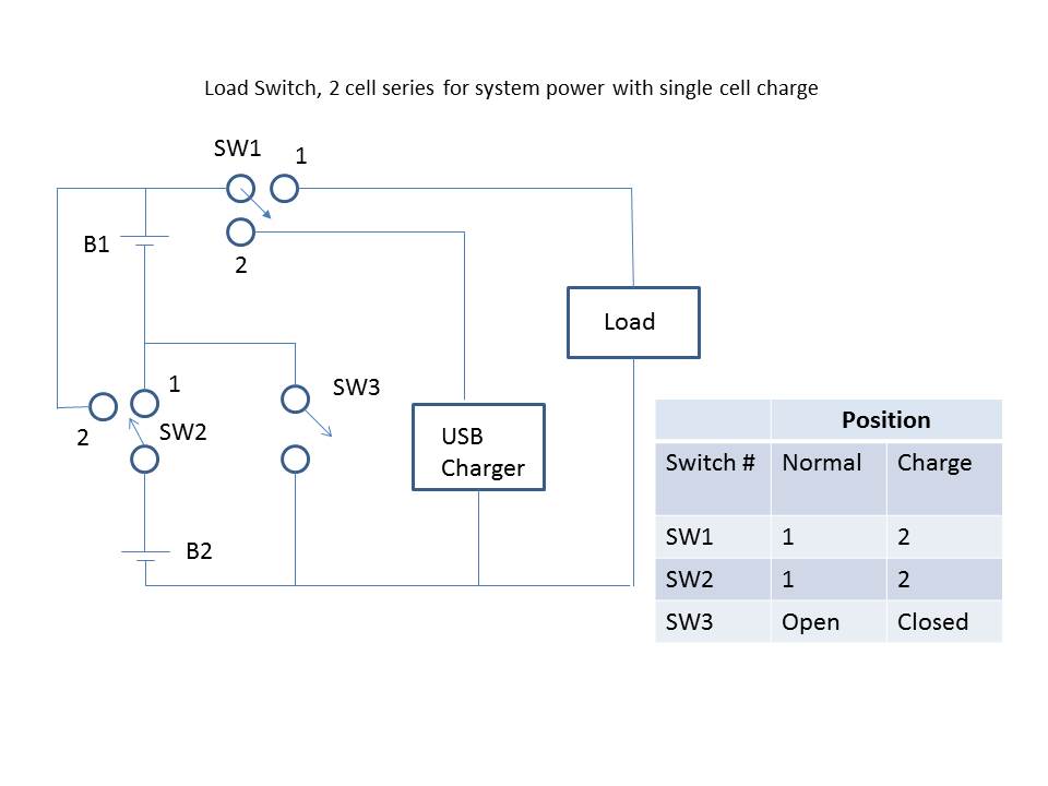
I have a need to charge two LiPo's from a USB port. The application is a simple micro-controller with a motor driven vacuum pump. The total load current is ~125mA for <=30s with a frequency of operation of about 8x per day. The system will automatically detect the presence of a USB connection and there is no need to drive the load during a charge cycle. Charging current can be limited to ~100mA or less if necessary. In the circuit below the idea is to configure the batteries in parallel during the charge cycle and in series when powering  the load. I have been investigating TI load switches but they all appear to be limited to a Vin of 8V and two fully charged Lipo's can reach 8.4V. The problem child is SW1 during normal operation.

In any case, it was suggested that I post this in the battery management forum to solicit suggestions to other solutions. Basically I need to charge and balance two Lipo's using a USB connection and be able to isolate the load while charging.  Any suggestions for a simple solution?

Thanks, Mark

  • Hello Mark,

    I have my concerns with your design. There is no guarantee that the batteries will be at the same voltage when you configure them in parallel for charging and even the smallest voltage difference could result in very large pulse currents.

    Would you be open to the idea of placing both batteries in parallel to charge and when the load needs power you could boost the battery voltage up the voltage needed for the load? This would simplify the control drastically by eliminating all of the switched and removing the concerns of differences in cell voltage or switch configurations that could short a battery to ground.

    The boost converter could even be run while the system is charging.

    Let me know your thoughts.

  • Thank you Ryan. I need to supply about 150mA to a 6V vacuum motor. I would be open to suggestions regarding a step up converter design. In the meantime I am looking at the Fairchild IntelliMAX Load Switches. The FPF2101 has a current limit of 200mA as well as thermal shutdown. The switches come in an SOT23 package which seems small enough. Better still would be multiple switches in a single package. I do have a concern over some of the bias conditions and if I will get a good turn on under all conditions. I should know more today.

    Let me know on the boost converter. Thanks

  • Hello Mark,

    You could look at the TPS61041 or TPS61040. These are simple boost converts that provide good efficiency with minimal external components and provide with with a simple single pin enable/disable control. They also are capable of boosting over the whole range of the battery voltage.

    You might otherwise consider the TPS61045 which is capable of disconnecting the input from the output which might be beneficial depending on how you are planning on dealing with the back EMF of the motor when you shut it down after it has run.

    Also one of the these switching converters will cost you less than one of the FPF2101 which since you were looking at 3 of those devices will save you a reasonable amount of money.

  • Hi Ryan,

    I could use a little guidance on my calculations. Is it correct that fS(Iload) will typically be higher than fSmax? For the TPS61041:

    Given: Single cell Lipo; Vin_min=3.4V; Vin_nominal=3.8V; Vout=6V; L=22uH; Vd=0.3V; Iload=120mA; efficiency=86%; TPS61041 application equations

    Calculations:

    Ipeak=250mA+(3.8V/22uH)(100nS) = 267.27mA

    fS_max=((3.4V)(6V-3.8V))/((267.27mA)(22uH)(6V))=212.02kHz

    fS(Iload)=((240mA)(6V-3.8V+0.3))/((267.27mA)2(22uH))=381.79kHz

    Iload_max=0.86(267.27mA2)(22uH)(212.02kHz)/(2(6V-3.8))=65mA

    I was thinking that the available load current would be closer to the quoted switching current of 250mA. If I go with an inductor of 47uH, my fS_max is 103kHz, fS(Iload) is 192KHz, and Iload_max is 63mA.

    Is there a way to squeeze more current out of this converter? I need about 120mA.

    Thanks,

    Mark

  • Hello Mark,

    I would like to preface this post with the thought you should look into the LMR62014. It is a higher current device that would have similar functionality and looking at some of the Efficiency curves should be able to give you the efficiency that you are looking for or possibly even better:

    However if you are interested in trying to make the TPS6104x family work here are some thoughts below:

    The simplest way to squeeze more power from a similar design would be to move from the TPS61041 to the TPS61040. The 040 has a higher switch current limit and lower on state resistance so it can both handle the higher current and it might even yield better efficiency.

    Regarding the capabilities of a design and debugging your component selection I have been playing around with the Excel design tool in the link below:

    http://www.ti.com/tool/tps6104xcalc

    This calculator will run through the equations that you have been working with from the datasheet only it will allow you to test options faster.

    Is your 120mA a constant load or is that a peak load?

    I ran through an example to see if it could fit your application.

    Vin=3.4V

    Vout=6V

    L = 3 uH

    Vd = 0.3V

    Ilim = 400mA

    Eff = 86% (Not sure if this is feasible but I took the desired number for your post.)

    This gave a peak switch frequency of 960kHz and a max output current of 125mA.

    What happens in this converter is that as the load current shrinks it will slow the switching frequency to improve low power efficiency.

  • Thanks Ryan,

    I took your advice and will try the LMR62014. The 61040/41 cuts it a bit close for my requirements. In addition, I would like to be able to bump the output up to 9V,150mA instead of 6V.

    I used the WEBENCH tool and it seems to work pretty well. My BOM cost is less than a buck.

    Mark