Because of the Thanksgiving holiday in the U.S., TI E2E™ design support forum responses may be delayed from November 25 through December 2. Thank you for your patience.

This thread has been locked.

If you have a related question, please click the "Ask a related question" button in the top right corner. The newly created question will be automatically linked to this question.

Bipolar output

Other Parts Discussed in Thread: LM3481, LMR62014, TPS54160A

Hello,

I am looking for a switching regulator solution that can deliver +14 V and -14 V from a +5 V input (4.5 V to 7 V range). Each output should feed a 330 mA load. This need to be made with two separate regulators, or there is one switching regulator with internal switches that may control both outputs? 

See you,

Oscar

  • You can do it with a boost converter that has a negative charge pump circuit added.  You will need something with a 2.5 amp switch current limit.  Let me see if I can dig up a schematic example.

    The LM61428 might work but I haven't designed with it before.  The LM3481 is a controller and it would definitely work.

    Regards,

    Marc


  • Normally, single chip A charge pump circuit is limited to 100 mA...

    The LM61428 can be used as a booster or other part like the LMR62014 (there is EVM described by the application AN-2183 that can be used).

    But for the negative supply, the LM3481 needs an external switch. For this supply I am looking at the TPS54160A family. The inverting configuration is not supported by the available simulation tools and It is necessary to design by hand...

     Regards,

    Oscar

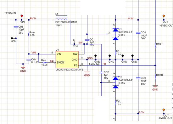
  • Here is an example of how to make a negative charge pump from a boost .

    asdaa

  • The positive rail comes from the standard boost circuit.  D2, CC2, R2 and C02 form the charge pump circuit to create the negative rail. 

    When the switch goes high CC2 is charged through D2.  Then when SW goes to the bottom of CC2 goes negative  Pulling the Co2 bottom terminal negative.

    This should be simulatable with the spice models.

    Sorry I didn't have time to make a clean schematic, I grabbed this from a different design.

    Regards,

    Marc

  • I've used the circuit you've shown for many years to power headphone amplifiers using the LM2733X, but minus R1 and R2.  I'm now working on a headphone tester that incorporates the same design, but if the load is ever too high, for example from a headphone with low resistance or a short, the LM2733X gets into an unstable mode where it continually shuts down and tries to restart.  Removing the load doesn't fix it and only power cycling or pulling SHDN low corrects the problem.  I've tried adding R1 and R2 with no effect, except that I can see R1 (a 1206 anti-surge resistor) start to glow after a few seconds indicating there is quite a bit of current going through it.  The regulator gets pretty hot also.  Any Ideas on how to protect against this or at least cause it to reset when an excessive load is removed?