This thread has been locked.

If you have a related question, please click the "Ask a related question" button in the top right corner. The newly created question will be automatically linked to this question.

TL431 stops conducting as Vref increases

Other Parts Discussed in Thread: TL431

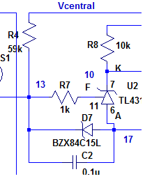
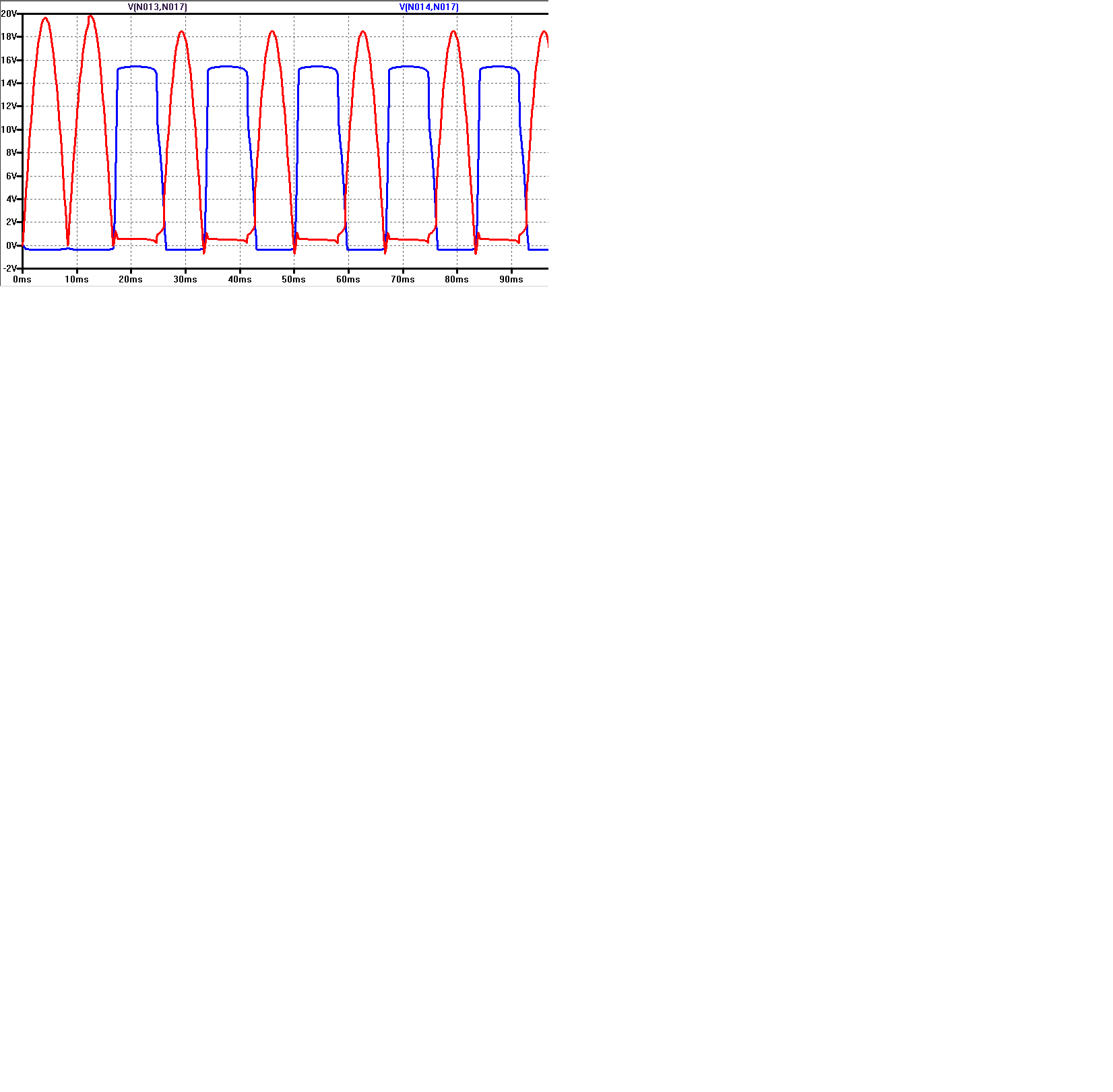
Hi, we are using Tl431 as comparator.  Under normal conditions we have 22V  AC pk at Vk-a.  As Vref (Vg-a) reaches 2.5V it starts conducting as intended, Vk-a goes to near zero.   Under certain fault conditions we have Vref reaching higher voltages, up to 180V AC peak for up to few mSec.  To prevent Vref from getting too high, we have a 15V zener from Gate to Anode to keep Vref at 15V or below.

When fault condition occurs, we are noticing that before Vref reaches 15V , TL431 stops conducting, i.e. Vk-a goes from near 0 to 15V.  

Any idea on what the maximum voltage allowed is at Vref (Vg-a)  is?  Putting 1k in series with the gate makes the problem go away.  However at -35C we are still seeing the problem even with 1K at the gate.

  • Petar,

    A series resistance on reference pin is needed when TL431 is used as a comparator because the reference pin  conducts to cathode when Vref - VKA > one diode drop (about 0.6V at 25C). Therefore Vref current must be limited to a low level. 

  • Hi Ron, thank you for your reply. 

    We had a 15V zener from Gate to Anode  and a 1K between zener cathode pin and TL431 Gate to limit the current. At room temperature, Vka was negligible TL431 was conducting, Spice model was in agreement with real sample scope shots.   However we got into trouble at low temperatures.  At -35C Vka grew too much for our application.  With a 5.1V zener and a 1K series, we are seeing only few volts of Vka at -35C.  So this works for us.   

    Any idea how to get the Spice model to show what you said about current flowing from ?

    We get same voltage from either side of R7 to TL431 Anode even when Vka < Vref by more than a diode drop.  

    Black and Blue are Vref on either side of 1K. Red is Vka

    Spice model to TL431

    .SUBCKT TL431 7 6 11
    *             K A FDBK
    V1 1 6 2.495
    R1 6 2 15.6
    C1 2 6 .5U
    R2 2 3 100
    C2 3 4 .08U
    R3 4 6 10
    GB1 6 8 VALUE = {IF(V(3,6)< 0 , 1.73*V(3,6) -1U , -1U)}
    D1 5 8 DCLAMP
    D2 7 8 DCLAMP
    V4 5 6 2
    G1 6 2 1 11 0.11
    .MODEL DCLAMP D (IS=13.5N RS=25M N=1.59
    + CJO=45P VJ=.75 M=.302 TT=50.4N BV=34V IBV=1MA)
    .ENDS

  • For some reason the pictures did not get posted.

  • Petar,

    I highlighting the diode in red. 
    As Reference pin voltage exceeds 2.5V the cathode should drop to about 1.9V and reference current increases.

    What is the full part number that you are using?
    Is node 17 ground? 

  • Hi Ron,

    we tried TL431AI, and TL431BI,   Node 17 is not ground, it has another 5k to ground. 


  • Petar,

    With 5k to ground in anode. the device becomes an linear amplifier instead of a comparator. 
    Anode voltage will try to be Vref -2.5V. the cathode current will match anode current. Once VKA drops to 1.9V, REF to cathode will forward bias and anode current will increase without an increase in cathode current.

    I tested a grounded anode comparator with RIN = 2k and cathode to 15V via 10k resistor down to -80C without any problems on TL431BI.