This thread has been locked.

If you have a related question, please click the "Ask a related question" button in the top right corner. The newly created question will be automatically linked to this question.

TPS65217C unexpected behavior

Other Parts Discussed in Thread: AM3354

Hi,all

My customer is happend unexpected behavior at TPS65271C .

TPS65217C is the state of ACTIVE,
Do you know the cause of the SYS pin (pin 7, 8) falls to 0V?
· AC pin (10 pin), + 5VDC has been applied.
· USB pin (pin 12) is not connected.
· PWR_EN pin (pin 9) is the state of the High.
· I am connecting the VLDO1 pin (pin 3) in the PWR_EN pin (9 pin).

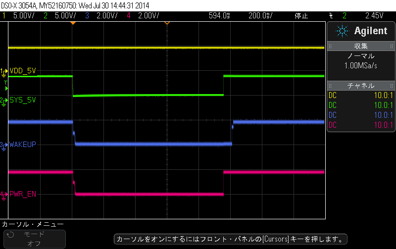
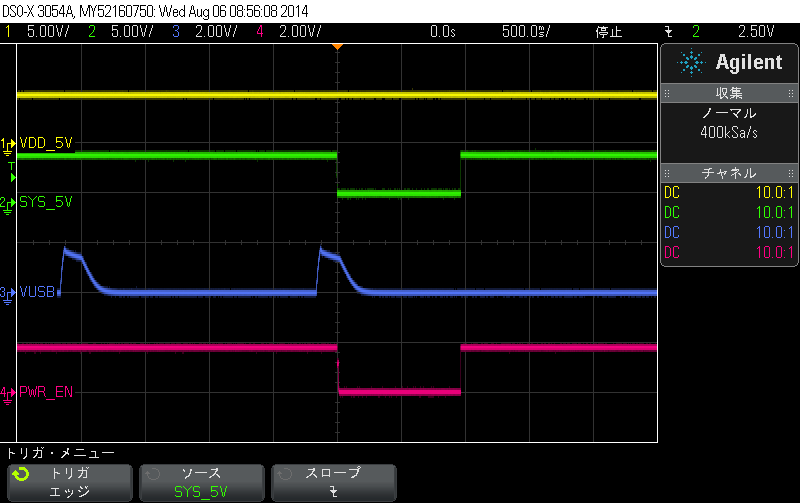
Attached is what was captured to observe the pin with an oscilloscope.
VDD_5V  (yellow) ---> AC pin (pin 10)
SYS_5V  (green)  ---> SYS pin (pin 7, 8)
WAKE_UP (purple) ---> nWAKEUP pin (Pin 13)
PWR_EN (pink), PWR_EN pin (pin 9) = VLDO1 pin (pin 3)

After the SYS pin fell to 0V, and then the VLDO1 & nWAKEUP fell in Lo, the SYS will rise after about one second.

This phenomenon is confirmed in multiple boards.
This phenomenon is happened after few hours, after power on.
And this phenomenon is happening repeatedly.

There was a similar symptoms at the following site, but there is no description of the solution.
http://e2e.ti.com/support/arm/sitara_arm/f/791/t/305879.aspx

But my customer didn't use BBB.

Can your suggest me any workaround?

Best regards,

  • Ito-san,

    I have tested this configuration myself and not been able to see this behavior.  It appears there is something causing a reset of the device.  When a reset occurs the PMIC shuts down for 1s and then restarts as seen in your scope capture.

    Can you please provide a scope capture showing the nREset pin, PB pin, VSYS, and LDO1. With a capture zoomed in on the falling edges so I can see the timings.

    Thanks,

  • Watkins-san

    Thanks for your quick reply.

    My customer confirmed the SYS pin (pin 7, 8) falls to 0V,when USB_OTG of AM3354 connect to USB of TPS65217C.
    Please confirm attached figure.

    1.VDD_5V(yellow)-------------AC pin (pin 10)
    2.SYS_5V(green)-------------- SYS pin (pin 7, 8)
    3.VUSB(purple)---------------- USB pin (pin 12) : Connect USB0_VBUS pin of AM335x (P15 pin)
    4.PWR_EN(pink)--------------PWR_EN pin (pin 9) : Connect VLDO1 pin (pin3)

    The failure doesn't occur,when they do not connect the USB_OTG to the USBpin.

    Would this connection be the cause of the problem?

    Best regards,

  • Ito-san,

    Is there a battery being used in this application?  In situations that do not use a battery, we do not recommend using both the AC and USB pins.  When a battery is not present the device will have difficulty switching between the two inputs.  Please see page 25 of the datasheet.