This thread has been locked.

If you have a related question, please click the "Ask a related question" button in the top right corner. The newly created question will be automatically linked to this question.

TPS62172 oscillating after input crowbar

Other Parts Discussed in Thread: TPS62172

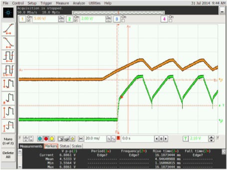
We use the TPS62172 with 30uF on Vin, a 2.2uH inductor, and 20uF of capacitance after the inductor.  FB is grounded and EN is tied to Vin.  The input voltage is 15V.  We appear to be getting some oscillations in the output voltage at temperatures around 85 deg C during our crowbar tests, where we short the input voltage for 10-15 seconds before releasing the short.  Not all units exhibit the oscillations.  Even those units that oscillate do not oscillate after every crowbar test.  We current limit the supply to 100mA for the crowbar test.  Our "normal" load is roughly 20mA. 


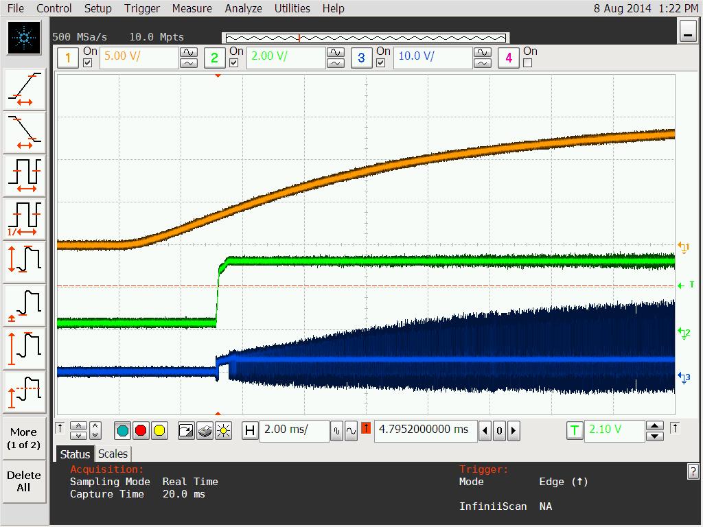
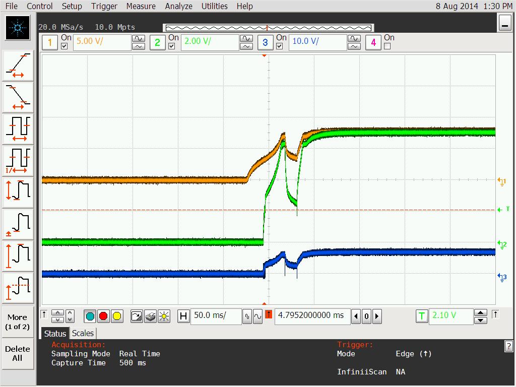
The during oscillation, the output voltage is between 6.3V and 2.5V, roughly.  Any idea what can cause this oscillation?  Is it related to the rise time of the input voltage?  How do we prevent the oscillation?  We do not see any oscillations when the supply is turned on, oscillations only occur on power up during the crowbar test.

Thanks.

KTM

  • Please post a waveform of Vin, Vout, and SW when it oscillates.

    What load is present during the test?  What dielectric caps are you using?

  • Chris,

    Thanks for the prompt reply.  Attached are Vin and Vout.  We didn't capture SW earlier but may be able to do so.  The load is a microcontroller drawing about 20mA at 3.3V.  The caps are ceramic X5R dielectric.

    KTM

  • Thanks for sending.  If it is possible, please add the SW pin to the waveform.

    As well, code you take a picture of the IC to see its markings on the top?  It would be good to confirm that it is a TPS62172.

  • I'll work on getting the picture.  The top of the part shows

    QUG

    33K

    AF7H

  • Sorry about the delay - it was difficult to get a temperature chamber.

    The first set of plots was taken at 80 deg C at initial power on (i.e. not a crowbar test).  Trace 3 is SW.

    This set of traces shows another mode that we sometimes see after a crowbar test at 80 deg C.  The power supply was current limited to 200mA.


    Again, this failure to regulate does not occur on every board and appears to occur only over a limited temperature range (roughly 80-85 deg C).  The power supply supply appears to ramp up faster for initial power on versus the crowbar test.  Would this be causing problems?  Any help in troubleshooting would be most appreciated!

    Thanks.

  • Thanks for the date code and waveforms.  It is a TPS62172 device.

    Was the second waveform showing it recovering from the crowbar test?  If not, could I see this--Vin going to some near 0 level and then coming back up?

  • Yes, the second set of waveforms is for the regulator recovering from the crowbar test.  In this instance the output of the regulator did not go into oscillation but does settle at roughly 7V instead of the desired 3.3V.  Note the difference in time scales between the two sets of plots.

    Thanks.

  • Thank you for your patience.

    I did some checking and confirmed that your ICs are from March 2013 which is around when we issued the attached PCN for these devices.  8308.PCN20130130000.pdf

    So, I recommend ordering new samples from our sample room to be sure you are testing the latest production material.  Let me know if you need help with this.

  • Thanks for the information.  I will pass this along to the board designer.  Is there any more information on the problems or symptoms that caused the changes to the part?  It would be informative to know if we are seeing similar problems.

    Thanks again.

  • As noted in the PCN, we did not change any electrical spec or item that would affect the form, fit, or function of the device.  We sometimes do changes like this to improve yields, reduce test time, etc.

    Your input bus short is not a very common test situation, so I would describe it as a 'corner case'.  (I can't remember seeing anyone else perform this test on any device, for example.)  Since you see a behavior at the highest temperature and only sometimes on some units, this pushes it further out into a corner.

    I would just recommend that you test your prototype with our latest production material.  In general, this is a good practice.

  • Thanks again for the previous responses to my postings. I have a few follow up questions.

    We have been troubleshooting some systems with the old regulator that now draw high current as the temperature ramps to 85 degC at roughly 3 degC/min. There is no crowbar action (input bus shorting) being performed. The board with the regulator is potted, so it is difficult to make an measurements. I have been asked to determine the possibility that the old regulator is failing to regulate, causing a high current condition because of a higher output voltage.

    Does your experience with the old regulator indicate that it may fail to regulate and go into a higher or lower voltage output mode during temperature ramp testing as described above?

    Also, could the failure to regulate during a crowbar action (as mentioned in earlier postings) cause damage to the regulator, making it more susceptible to regulation problems during temperature ramp testing?

    Thanks again.
  • We need measurements of Vin, Vout, Iout, and Iin to know for sure if the IC is being less efficient than it should be.

    No, I don't know of any errata related to a temperature ramp.

    If you have input crowbar events, these sometimes create ringing above or below the abs max rating of the Vin pin of the IC. This can possibly result in damage.