Because of the holidays, TI E2E™ design support forum responses will be delayed from Dec. 25 through Jan. 2. Thank you for your patience.

This thread has been locked.

If you have a related question, please click the "Ask a related question" button in the top right corner. The newly created question will be automatically linked to this question.

Configuration of BQ24192

Other Parts Discussed in Thread: BQ24192

Hi,

I'm planning to use BQ24192 in a circuit application. This is my scenario:

* 5V-3A source connected to VBUS;

* Single-Cell Li-Ion battery connected to BAT
         - Fast Charge Current = 2A;

         - Pre-charge and termination current = 256 mA;
         
         - Voltage charge = 4.2V.

* At least 3.7V in SYS output.

Questions:

1. Considering REG01[7] = 0 (as set by default), all previous set register values will be kept by BQ24192 during a second power-up?

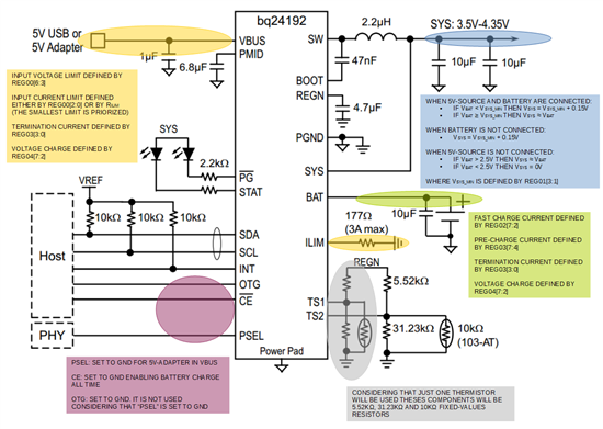
2. Are all information shown below correct?


3. In our case, for the specified input, output and battery charge scenario we just have to change:
               
    REG00[6:3] = 1111;
   
    REG01[3:1] =  111;
right?
Thank you!
  • Hi Luiz,

    1 -

    Writing a '1' to Reg01[7] will reset all the register to their default state, but leaving it a '0' will not fix the register values after a full power reset.  If you remove both the battery and input source from the device, when it is powered up again all the register will have their default values. 

    2 - 

    I think you have done an overall good job of summarizing the correct registers and functionality in your annotated diagram.

    3 - 

    I would not recommend writing REG00[6:3] = 1111 (5.08V).  This register sets the minimum voltage level allowed by the VINDPM function and when the adapter voltage falls below this value, the device will reduce the charge current to maintain the selected VINDPM minimum voltage. There are details on how this feature works on page 24 of the bq24192 datasheet under the title " Dynamic Power Management."  

    The default register value is probably acceptable in your application depending on your system load range.

    Please let me know if this help or if you have any further questions I can help you with!


    Best,

    Rachel 

  • Hi Rachel!

    Thank you. You helped me a lot!
    I'd like just to ask you one more question: my output voltage range reading, shown in the diagram, is correct? Taking into account whether battery and input source are present or not.

    Again, thank you so much.