


Hello,
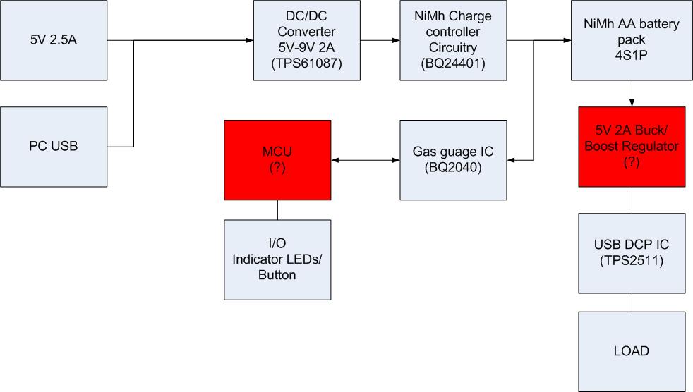
the block diagram below is for a NiMh battery bank, which is intended to work with standard off the shelf NiMh batteries.
Features
The design is intended to have the following features
- Powered by 4 AA NiMh batteries in series with a charge voltage of about 9V.
- Power is to be supplied from a 5V 2.5A adapter, or from a PC usb port.
- 4 level charge level indicator which will be indicate charge state when charging or discharging. However when idle, the LEDs will be off and will only be activated for a few seconds to indicate battery charge when a push button is pressed.
Components
- I have selected the TPS61087 as a DC/DC converter to convert 5V to 9V to charge the batteries
- For the charge controller, i have BQ24401 because it appears to have a simple charge circuitry, as well as good price.
- To enable most mobile devices connect to the power bank, i selected the TPS2511 as the DCP controller.
- the charge indication i'm using the BQ2040 gas guage IC which will connect to a suitable low power MCU.
Challenges
- How can i draw maximum possible power from the PC usb port when charging.
- What Buck/Boost convert will suit this application to convert the batter voltage to 5V output for charging mobile devices with a maximum of 2A charge current
- What MCU is recommended for this application