This thread has been locked.

If you have a related question, please click the "Ask a related question" button in the top right corner. The newly created question will be automatically linked to this question.

BQ24257 D+/D- detection error

Other Parts Discussed in Thread: BQ24257

Hello,

We're using the BQ24257 in a new design. In stand alone mode USB detection doesn't seem to be working correctly. A dedicated USB-charger, capable of supplying 2.1A is sometimes recognized as charger and charges with the set current limit of 1.8A, sometimes it charges with a current of maximum 500 mA and most of the time the current is no higher than 100 mA.

We'd like to know why the BQ24257 doesn't recognize the USB charger consistently.

See the attached battery charger schematics. 

Regards,

Niels Kooy

BQ24257 Battery schematic.pdf
  • Hello Niels,

    With Dedicated charger port detected, bq24257 will set the input current limit to whatever is programmed by the external ILIM resistor. You have 100 ohm at ILIM pin which should give you ~2.7A ILIM, which is higher than your 2.1A charger limit. 1.8A sounds like the IC has correctly detect the DCP but for some reason the ILIM is limited by something else. What is the VBUS voltage?

    Also, may I know why you have R167, R174 and R175? Extra resistance on the D+/D- line is likely to affect the detection results. If the IC detects CDP or SDP and the battery is below 3.4V, the ILIM will be limited to 100mA due to the Dead Battery Provision for BC1.2.

    Thanks,

    Wenjia

  • Hi,

    R167 was placed in the design for testing purposes.. and removed quickly again! R174 and R175 were placed to make sure the pin wouldn't float. For this test these resistors are removed, so are R52 and R66 so the BQ24257 is the only device on the USB-bus.

    The current setting resistors are now changed to more appropriate values, RIlim = 180 Ohm and RIset = 270 Ohm. Fast charge current is limited to 0.92A and the input current limit is set to 1.5A. Vbus at the capacitor located closely to the input pin measures 5.02V.

    Result of the test is: the charging current is a stable 0.5A, so lower than expected. 

    Can you advice me how to increase the charging current in stand alone mode?

    Thanks,

    Niels

  • Hi Niels,

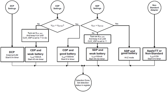
    In standalone mode, the input current limit is only determined by the D+/D- USB detection. Your external ILIM settings look correct, however it seems the IC doesn't detect DCP.. According to the below chart, looks like it detects non-standard adapter. Can you try shorting D+/D- together and see if you can get what you programmed ILIM and ICHG? This should put the device in DCP.  Just to make sure that the IC can detect the correct condition.

    .

    Thanks,

    Wenjia

  • Hi Wenjia,

    Thanks for the advice. Shorting the USB data lines results in a charging current that is set with the external resistors, so it is able to detect the correct condition.

    Can you advice me what to do next?

    Thanks,

    Niels 

  • Hi Niels,

    Then it looks like when D+/D- is not manually shorted, something else on the D+/D- lines prevented the device from detecting DCP correctly. Can you measure the D+ and D- pin voltage separately when you saw 500mA charge current? Also, what is the real input current and battery voltage with the 500mA charge current?

    Do you expect the device to connect to other USB ports besides DCP? If not, then shorting D+/D- will always program device in DCP. Also, if the R174 and R175 exist in real application, they will program the device in SDP all the time, which will give you 100mA ILIM when VBAT <3.4V and in hi-z when VBAT>3.4V.

    Thanks,

    Wenjia

  • Hi Wenjia,

    The voltage on both D+ and D- is 2.71 Volt when the charge current is 500 mA. The battery voltage is 3.82 Volt and the charge current to the battery it self is 500 mA, measured in the plus-connection of the battery itself. All components that have something to do with the USB-wires have been removed, including ESD-security for now, but it seems there's still something disturbing the correct DCP-detection.

    Unfortunately we have to be able to connect to a PC, so that suggestion is not usable. 

    Thanks for the support,

    Niels

  • Hi Wenjia,

    I've discovered that detection of a DCP charger doesn't work flawlessly when shorting D- and D+. Voltage on these lines when a DCP charger is correctly detected is 0.6 Volt. Disconnecting and reconnecting the charger is enough to lower the charge current to 500mA, with 2.71 Volt on both D- and D+. I need to disconnect the complete battery to make a charger connect as a DCP charger again. 

    I hope you can me with this!

    Thanks, Niels

  • Hi Niels,

    To be able to detect DCP, the D+ voltage need to be below 0.9V threshold for primary detection. Once the voltage is above 1V, the IC will detect non-standard and will limit the current to 500mA.

    I used a dedicate charger port and plugged it into the bq24257EVM, the signal on D+ and D- is as below. D+/D- is shorted together and the voltage is about 660mV. The current limit is determined by the external resistor.


    Do you have any idea why the D+/D- pin voltage is that high? Have you tried with different USB cable?

    Thanks,

    Wenjia