This thread has been locked.

If you have a related question, please click the "Ask a related question" button in the top right corner. The newly created question will be automatically linked to this question.

BQ24074 Buzz and dropout under moderate load

Other Parts Discussed in Thread: BQ24074

Hi, 

I've searched the forums and double checked the datasheet and my design but can't seem to find the issue here. I'm hoping someone could perhaps help me pin this down. 

I have designed a board using a BQ24074. The IC accepts a DC voltage and a Li-Po battery, and at its output is a DC DC boost converter which boosts the output voltage to 5V. I have tested the boost converter separately and it seems to work fine, so the problem seems to be with the BQ24074. 

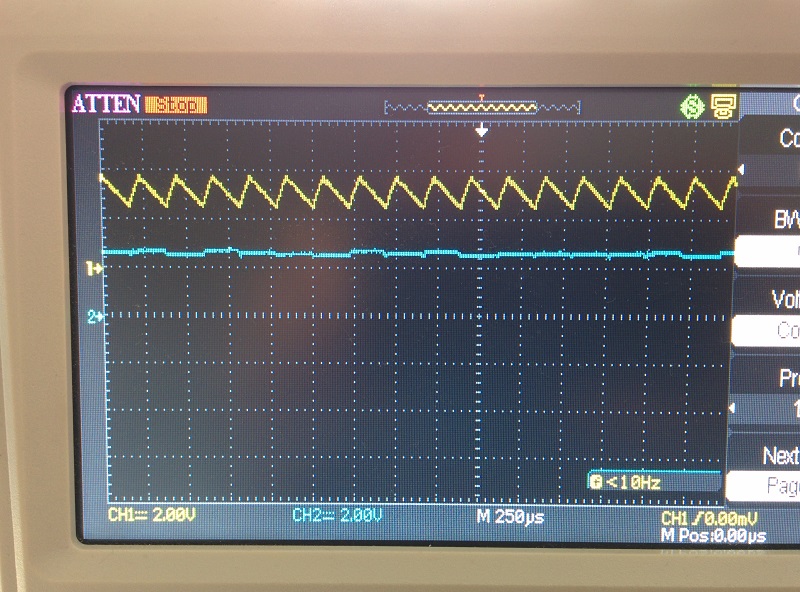
Everything works as expected while the load current is under about 0.8A. When I connect a load greater than 0.8A, and the BQ24074 is running only off DC power (no battery present), the IC immediately starts to emit a high pitch noise, its output drops to about 3.5V (from expected 4.4V), and the "charging" LED lights up (power good LED is always ON on DC power).

If running only off the battery, (no DC supply present), it sources the required current and everything works as expected. If running on both DC power and battery, it also works as expected.

It seems like it is running into some kind of limiting mode, but I can not figure out why as I think I have configured everything correctly, and I don't understand why the "charging" LED turns on even though no battery is present. It is NOT a thermal issue as the IC is heavily heatsinked both by copper and an additional top mount heatsink - it is not getting uncomfortably hot to the touch either.

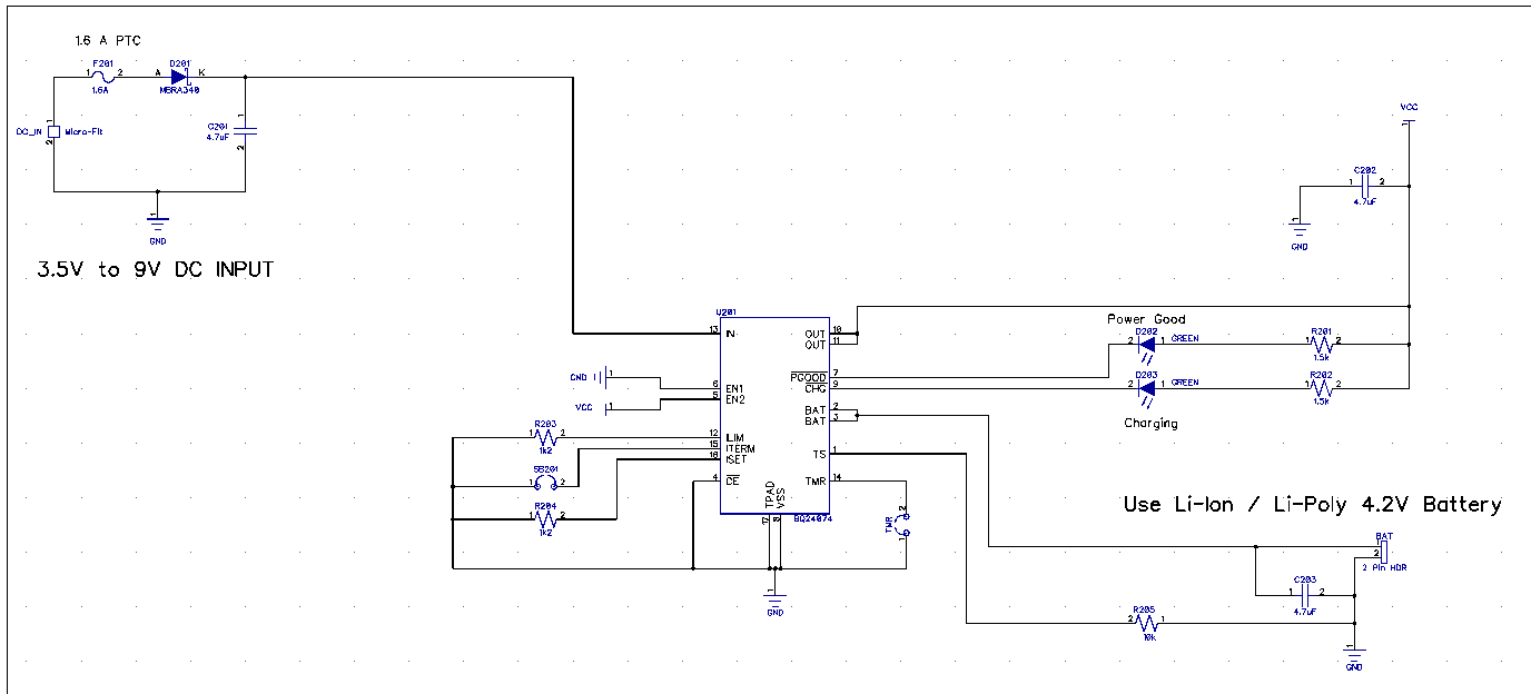
Relevant part of the schematic is attached. 

Any clues?

Thanks in advance,

Regards,

-Igor 

  • Hi Igor,

    Your schematic looks correct. Can you help provide the VIN voltage when the output drops to 3.5V and the waveform of the noise? Also, this device has battery detection routine, so can you verify that VBAT has the signal as shown in Figure 3 on the datasheet?I want to make sure that the IC didn't incorrectly detect the battery.

    Thanks,

    Wenjia

  • Hi Wenjia, 

    Please see images below: 

    This is a normal operation with a 5 Ohm load on the output of BQ24074. Yellow trace is vout, blue is vin from power supply.

    This image is also proper operation with a 5 ohm load, showing vout (yellow) and vbat (blue) (battery detection routine seems to be running). 

    This image shows signals under the fault condition (3.3 Ohm load at the output of BQ24074). Vout (yellow) - notice it has dropped a bit from previous image, and vin (blue) from power supply.

    This image shows operation under fault condition again (3.3 Ohm load at the output of BQ24074). Vout (yellow), and vbat (blue). Seems like battery detection routine is not running anymore? 

    The last image shows the full system (with boost converter). In this instance, the 5.5V output of the boost converter was loaded with a 5 Ohm load, and the yellow trace shows the output of the BQ24074 (which should be 4.4 V or thereabouts). Notice how it is sawtoothing? The blue trace shows the vbat signal under this condition when the full system is loaded. 

    I tried changing the frequency of operation of the boost converter at the output of the BQ24074 hoping some kind of resonance is happening, but the same thing occurs regardless of boost converter frequency. I also tried adding 100uF capacitance between the output of the BQ24074 and input to the boost converter but no difference. It just seems the BQ24074 immediately enters this fault mode when directly loaded with 3.3 Ohm resistance, or when the whole system is loaded with 5 Ohm (or less) resistance. When the whole system (boost converter) is loaded with 5 Ohm, the output of the BQ24074 exhibits that sawtooth form, but when the output of the BQ24074 is directly loaded with 3.3 Ohm, the output voltage drops to about 3.9V but at least the sawtooth does not appear. However in both instances the BQ24074 lights up the charging LED and drops the output voltage. This happens on 4 identical boards so there is slim chance it is a soldering issue. 

    Note this does not happen when the battery is present and everything works fine even with heavy loads with the battery. However, at moderate and heavy loads without the battery the fault occurs. 

    Any clues?

    Thanks, 

    -Igor

  • When the battery is attached, the IC runs in supplement mode so that it provide the input current for the boost current.  When the battery is not attached, it appears that the charger cannot provide the current necessary.  Is EN2=1 and EN1=0?  Is the ILIM resistor set so that the charge can provide enough current (i.e. 4.4V/3.3ohm = 1.33A)?  If so, what is the voltage on the charger's IN pin during this time?  Is it drooping due to large line resistance and therefore entering VINDPM and/or dropout?

  • Hi Jeff, 

    You gave me the answer, thanks. It was the combination of the two, I changed the ILIM resistor to 1.1k from 1.2k to allow upto ~1.4A input current, and then the problem was still happening. Measuring VIN at the PCB instead of the output of the power supply sure showed a voltage drop in the leads which caused the IC to enter dropout. Bumping the supply voltage from 5V to 6V then provided the load with required current at the correct voltage. 

    Thanks for the help, 

    Cheers, 

    -Igor