This thread has been locked.

If you have a related question, please click the "Ask a related question" button in the top right corner. The newly created question will be automatically linked to this question.

BQ24250 switching frequency

Other Parts Discussed in Thread: BQ24250

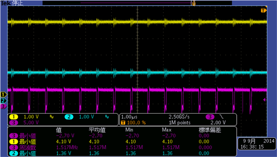
Attached figure is normal switching wavefrom for BQ24250.

Yellow:VSYS, Magenta:SW.

There is no VBAT, however VBAT is 4.0V (Expecting CV charge). And load current of VSYS is 0.5A.

In this case Fsw is almost 1.5MHz, not 3.0MHz.

I understand this device is fixed frequency of 3MHz. Is there any reason why it become 1.5MHz?

P.S.

Also observed bad load regulation when BAT is removed from this condition, it hits under VSYSMIN,

 but I will check this frequency first.

  • Hello Keiichi,

    I didn't find any attachment to the post, can you please attach the waveform again?

    Without a battery connected, there will be a battery detection routine happening and you will see a square wave on system pin and the battery will follow system voltage.

    I did some verification with the EVM but was not able to see 1.5MHz frequency. Let me take a look at your plot and see what we can find.

    Thanks,

    Wenjia

  • Hello, Wenja

    Attached is waveform, we can see 1.5MHz switching and Duty cycle seems enough to maintain PWM.

    As for battery detection routine, we also observed, but hitting Vsysmin is very first response within 15ms

    just after battery removal. I would like to confirm this 1.5MHz first and then proceed to response because

    1.5MHz (with 1uF) is not our expectation.

    Yellow:VSYS, Magenta:SW. Please ignore blue line.

  • Hello Keiichi,

    Let me make sure that I understand you correctly. You have 5V applied at input and 50mA load from system. Originally you have battery connected, however, within the 15ms after you removed the battery, you saw system voltage dropped to Vminsys and the SW frequency is 1.5MHz. Is it correct?

    Can you let me know what is the condition you have on VIN, VBAT, VSYS when the above waveform was captured?

    Thanks,

    Wenjia

  • Hello, Wenja

    Thank you for your quick reply.

    VIN in 5V by AC adapter. The system load is 500mA. The VBAT is true battery and seems CV.

    Before battery removal switching frequency is 1.5MHz not 3MHz. And then removing battery.

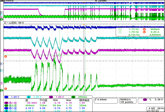
    The waveform just after battery removal is below.

    Blue:Vin, Cyan:VSYS, Magenta:VBAT and Green is IVIN.

    From this waveform it can see bad response when removing battery. These is many unknown phenomena,

    (i.e. If  VSYS drops just after removing battery, it seems in supplement mode before battery removal, but

    this waveform shows VSYS>VBAT, I think it was in charge phase.)

    I understand 3MHz with 1uH and 1,5MHz with 1uH have different response, so I would like to confirm why

    fsw is 1.5MHz  before battery removal first. And then start investigate its response. 


  • Hello Wenja

    This is additional info. We can see 

    1. VIN=5V, SYS load=600mA, Charge disabled -> 1.5MHz switching frequency

    2. VIN=5V, SYS load=0mA, Charge enabled (Actual ICHG is 100mA) -> 3MHz switching frequency

  • Hi Keiichi,

    I was able to recreate the 1.5MHz frequency. What happened is when the duty cycle is above 94%, the minimum requirement of the 'OFF' time is not met, so one falling and rising edge is skipped. Under this condition, the system output should be stable too. Can you please verify that when this happens, the difference between VIN and VBAT (measured from the pin) is less than 800mV? If you increase VIN or decrease VBAT, the duty cycle will decrease and the frequency should be back to 3MHz.

    For the waveform that you posted earlier, why there's still a potential on VBAT after the battery is removed?

    Thanks,

    Wenjia

  • Hello Wenja,

    Thanks for your help. I understand the scenario why fsw become 1.5MHz.

    For potential VBAT after battery removal, I agree with you. I will confirm it to customer.

    Anyway, due to bad response, VSYS become below Vsysmin and then reset entire system is true story.

    (I found bad artwork on customer's board, however customer also found it can reproduce on TI's EVM, but

    possibility is low compare with customer's board)

    I have much waveform other than this, but the phenomena is very complex. I will summarize and then

    reply again.

    Thanks, 

  • Hello Wenja,

    I did several labo experimental and confirmed duplicating condition.

    The /CE should be high in order to see bad VSYS response during battery removal (and connect also).

    Sometimes in battery removal when /CE=H let VSYS below VSYSMIN at TI EVM.

    I think that the "supplement mode"  do something, but I cannot understand scenario.

    Could you let us know why it occurs? 

  • Hi Keiichi,

    Can you let me know what is your setup when this happened? I was able to see this about 10%  of the time when I plug in the battery. If you can consistently recreate it, please let me know what is your VIN, VBAT, IBAT, system load and any other special conditions. It will be very helpful for me to find an answer for it.

    Thanks,

    Wenjia

  • Hi Wenjia,

    According labo staff, they only reproduce when battery insertion, not battery removal.

    The occurrence is  1/20~30, almost same as yours. In our cases battery is 4.2V and VIN is 5V

    by labo's power(Stabilized power supply). also the system load will be 100mA.

  • Hi Keiichi,

    We are investigating this internally and I will send you email to discuss this further.

    Thanks,

    Wenjia