This thread has been locked.

If you have a related question, please click the "Ask a related question" button in the top right corner. The newly created question will be automatically linked to this question.

Sepic design help LM5001

Other Parts Discussed in Thread: LM5001, LM5022

Hello,

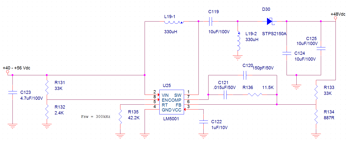
I am trying to design a Sepic circuit that will handle an input of 35V to 55VDC, with an output of 48V, 800 mA. Unfortunately Webench doesn't support sepic designs with the LM5001, so I have had to do my best to calculate the parts I need based on the limited information in the LM5001 data sheet and the 4Q 2008 article in AAJ by Jeff Falin, I came up with the following design:

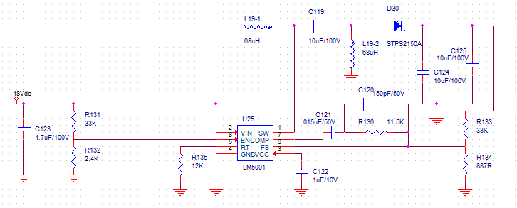
Unfortunately, after breadboarding the design, it appears to have a limit of about 130 mA instead of the intended 850 mA before it starts flashing on/off. The inductor is a Coiltronics DRQ127-680 dual coil inductor. I'm not exactly an analog or power expert, so I was unsure how to calculate ideal values for the error amplifier/comparator portion of the circuit. I just used the values that were given for the two Sepic examples in the data sheet.

If anyone could look at this design and let me know if they see any obvious issues that would be limiting me to about 130 mA on my 48V output, I would really appreciate it.

Thank you!

  • Update...

    I obviously do not understand how the sepic circuit is supposed to work. I assumed a higher switching frequency would result in greater efficiency and faster response time. However, out of curiosity I reduced my switching frequency to about 350 kHz and now I am able to drive my circuit without the switcher cutting out. It could have been an overheating issue (the LM5001 was getting extremely hot at 1MHz and it does not have a thermal pad to remove heat). At the lower frequency the heat does not seem to be as big an issue. The only issue now is that my output voltage has dropped significantly with the change in frequency. Checking my calculations with the slower frequency though, I see that I need a larger inductor value (I'll be changing to a 330 uH dual coil inductor) and I'm hopeful this will resolve my issue. Any additional feedback on this design and whether I have set it up properly would be greatly appreciated.

    Oh, I also noticed I had a schematic problem with my comparator/feedback circuit in the first image. I have corrected that as shown below.

  • Update...

    I built a new board with the 330uH inductor. I am able to get the 400 mA out that I need to drive my circuit. However, the LM5001 is extremely hot (case temp of about 80°C). My switching frequency is around 300 kHz. I intend to provide a much larger copper land for the thermal pad and I am hoping it will run okay, but I wonder if there is anything else I can do to reduce the heat that is being generated. Does the sepic design cause the LM5001 to work harder when the input is equal to or close to the intended output? How much does switching frequency effect temperature or power consumption?

    Thanks!

  • Hi Richard,

    The LM5001 is not able to support your application requirements for following reasons:

    1. For your application, max input voltage is 55V, and output voltage is 48V. LM5001 has an interal MOSFET which is rated at 75V. In SEPIC configuration, the voltage stress seen by the switch is VIN+VOUT=55+48=103V, which certainly exceeds the voltage rating of the internal MOSFET (75V). In practical circuit, there will some voltage spike on switchi, which makes it even worse.

    2. Your application requires 400mA output @ 48V. Even we assuming 100% efficiency and no current ripple at all, the input current at minimum VIN (35V) will be 48V*400mA/35V=1.09A. In a SEPIC converter, the switch current is the sum of input current and output current, i.e., Isw=400mA+1.09A=1.49A. In reality, the switch current will be higher than 1.49A when efficiency and current ripple factors are taken into account. However, LM5001 has typical 1A (0.8A miniumum) current limit, which is lower than your requirement 1.49A. That is why you can not get 400mA at output.  You mentioned that increasing inductance helped you get more current at output, that is because the higher inductance means the lower the current ripple.

    I would suggest you take a look at LM5022 controller, which is a good fit for your application.

    Thanks.

    Haifeng Fan