This thread has been locked.

If you have a related question, please click the "Ask a related question" button in the top right corner. The newly created question will be automatically linked to this question.

TPS61070 Startup issues

Other Parts Discussed in Thread: TPS61070, MSP430F5659

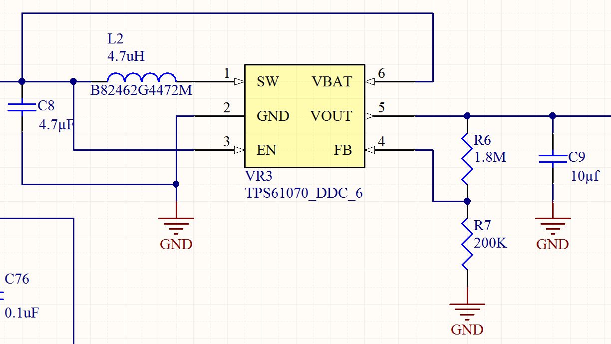
I've designed in a TPS61070 to step up a single cell lithium thionyl battery (2.8V-3.7V range) to 5V.  I've got a few board that work flawlessly every time I hook them up they automatically output 5V, and now the weird part.  Some of the boards I have will not start switching, it looks like they are in the pre-charge phase and I can't seem to get them out of that phase, while in that nonswitching phase I've looked at the FB voltage and it was around 600-700mV far above the 500mV that it should be.  I've tried switching out the FB resistors from 1.8Mohm and 200Kohm to 910Kohm and 100Kohm to increase the FB current in hopes that the circuit was just unstable.  I've also tried increasing and decreasing the input and output capacitance to no avail.  Most of that testing / trial and error was based on Page 5 of this http://www.ti.com/lit/an/slva387/slva387.pdf .  Also note, I'm only drawing maybe 10mA or so at startup, this 5V is supposed to feed my 3V and 3.3V LDO's which feed my processor (MSP430F5659) and other circuitry.  

Any ideas what would cause the TPS61070 to not start switching once the output capacitor was charged to Vin?

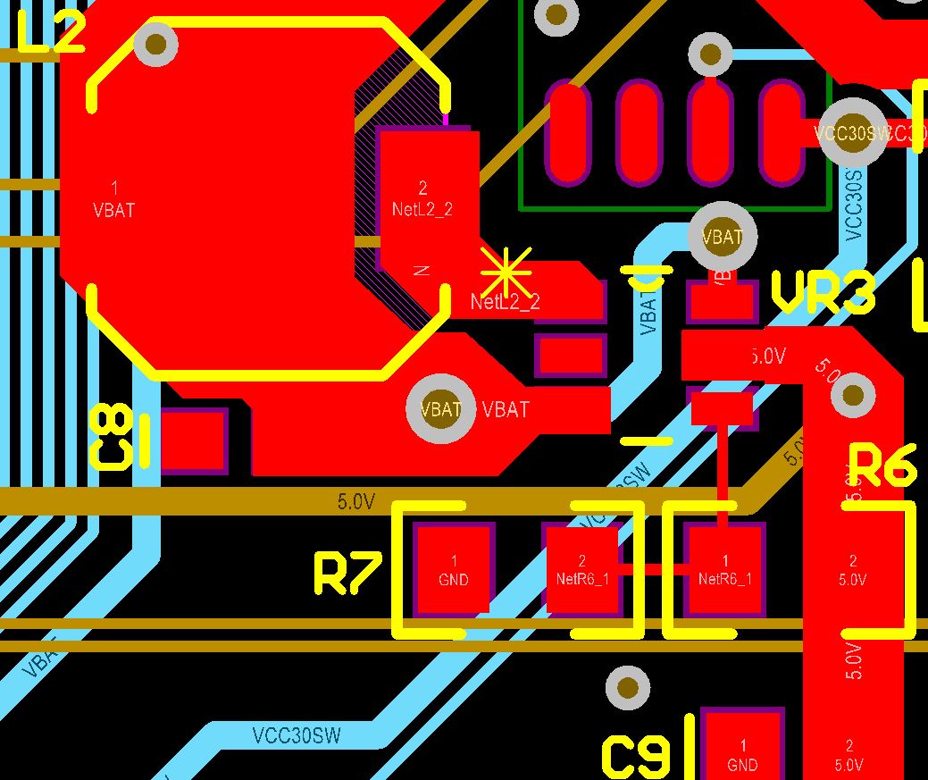
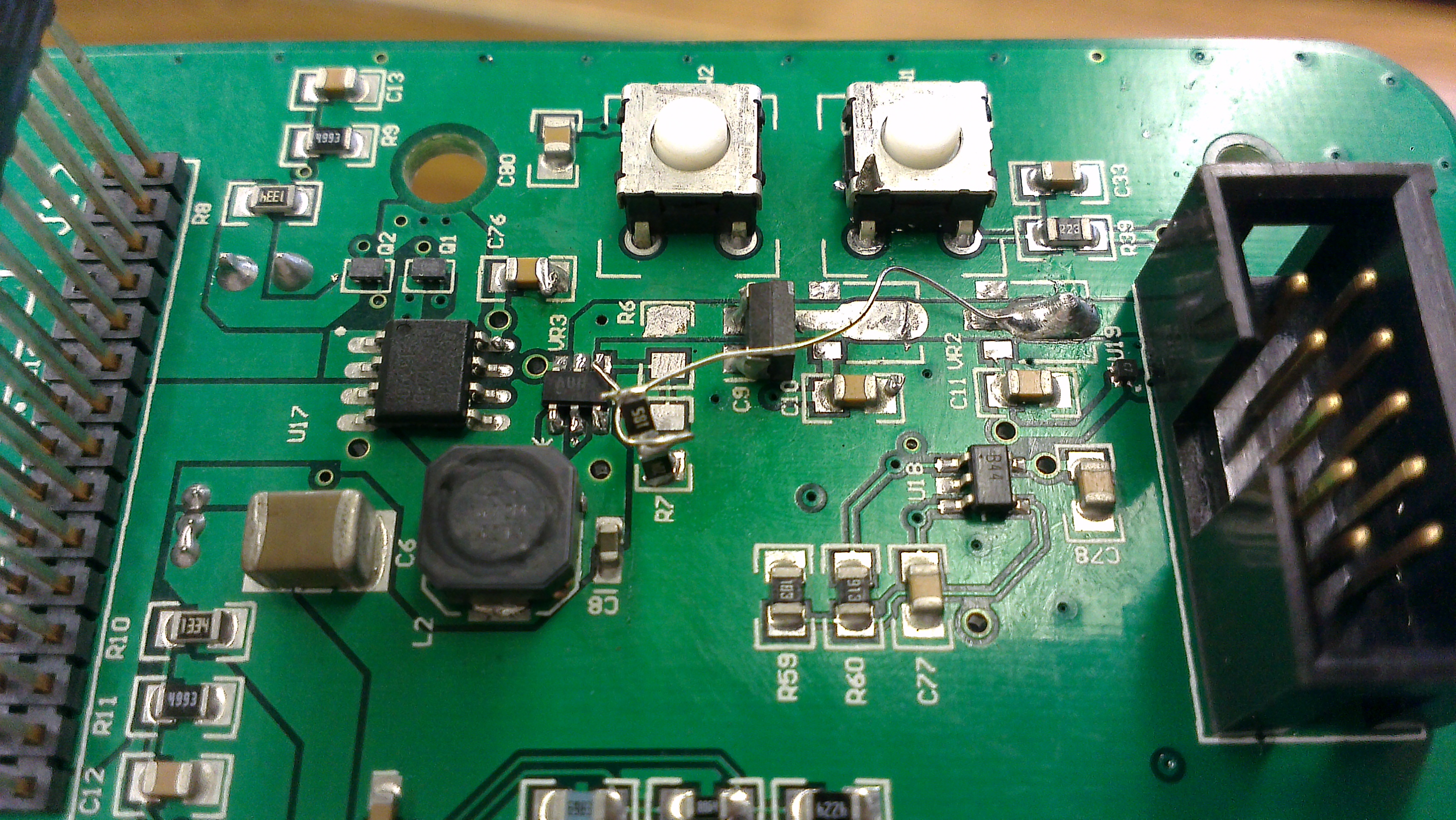
I've attached my layout and schematic.  On the layout, the ground pour is hidden, but it is connected.

Parts List:

The resistors are just standard 1%

KEMET C0603C475K8PAC   CAP, 4.7µF, 10%, 10V, X5R, 0603 1 C8
KEMET C0805C106K8PAC   CAP, 10µF, 10%, 10V, X5R, 0805     1 C9
EPCOS B82462G4472M   Inductor, 4.7 µH, 20%, 2 A     1 L2

  • Hi Drew,

    I am kind of worried about how far your output cap is from the IC.  It sounds like you may have a loop stability issue if you aren't getting regulation.  Seeing 600 mV on the FB pin also makes me suspicious about your stability.


    Can you move the capacitor C9 closer to your IC?


    Also, can you bring up the switcher with the load disconnected on these bad boards?


    Regards,

  • I moved it as close as I could, 

    This did not help anything, Vin = 3.3, Vout = 2.3

    It's almost like it's stepping down instead of up which is strange....

    Also, as you can see.  Disconnecting the load is a difficult task.  I actually blew off the part on a different board, bent the pin up, soldered it back down, and did something similar to this board and the results were about the same.  except that the output varied wildly.

  • After some more testing, I think the problem my be related to the FB.  I disconnected the load by blowing off some downstream regulators.  I put a 10uF output capacitor on C9.  I didn't mount the feedback resistors in their normal place, instead I did this (show in picture) to eliminate possible layout issues.  This FB is more similar to the EVM board layout.

    After I did this I tested the regulator, it actually boosts so long as my input voltage is 2V or less to an output voltage of around 3V.  While it was boosting I checked the FB voltage and it was 514mV which is not correct at all.  By my calculation it should be

    Vfb = Vout * (R7/(R6+R7))

    = 3V * (200000/ (1800000 + 200000))

    = 300mV

    not the 514mV I was seeing.

    That being said, the regulator is shutting off when my input voltage is getting closer to 3.6 which is where my batteries nominal range is.

    Any ideas?

  • VFB should be 500 mV typical.  TPS61070 will boost the output so that the fed back voltage at VFB is approx. 500 mV.  Are you really using 1.8 M?  What are your input and output specifications?

  • Yes, I checked the resistors before I put them in the circuit.

    The Specs are as follows Vin in production will be a Lithium battery so 2.8V to 4.2V, Vout needs to be 5V.  

    I calculated the resistors for the Feedback to be 1.8Mohm and 200Kohm which should give me 500mV when Vout is at 5V.  I checked this against the datasheet and it should be well within specs.  It said the FB pin needed a current of around 1uA and 5V / 2Mohm = 2.5uA so I assume I'm within the device specs.

    Update:  I just connected a wire from the ground on resistor R7 (my schematic, R2 in datasheet schem) to the input ground and my regulator started functioning, not fully, but way more than it was previously.  I'm up to 4.5V so I'm assuming this whole issue is a ground shifting problem or at least related to how my layout is grounded.

  • Right, If you are seeing 500mV on VFB and not 5 V on Vout, then you have additional losses somewhere.  So this is probably a layout / grounding issue.  Can you post your schematic and layout?

  • I see it is further up the thread...For some reason the previous bits of this did not open when I first replied.

  • I'm inclined it may be your C8 location.  It should be tied directly at pin 6 and connected to GND pin 2 with a short trace under the IC.  See the evm users guide.