This thread has been locked.

If you have a related question, please click the "Ask a related question" button in the top right corner. The newly created question will be automatically linked to this question.

Inverting Buck Boost toporogy of 300W

Guru 20090 points
Other Parts Discussed in Thread: LM25119, LM5119, LM5088

Hello,

Our customer request the following specification inverging buck-boost.
Could you please let me know the recommend DCDC and FET for the following requirement?
---------------
Vin:12V
Vout : -10.5V
Iout: 30A
---------------
I found the PMP8928 which is 65W inverging buck-boost reference design as maximum output power in PowerLab. 
> http://www.ti.com/tool/PMP8928
If we can't achieve above requirement , please let me know the problem.( inductor or diode ?)


Also I simulated these requirement by Power Stage designer.
As a result, we need the inductor about 0.5uH/63A. I think that this value is
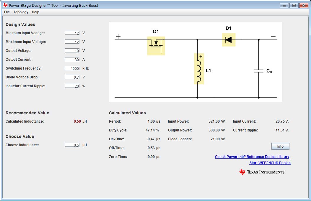


Best Regards,
Ryuji Asaka

  • Ryuji,

    I would consider a 2-phase buck controller for 30A output (15A per phase).  LM25119 reference designs are a good place to start.   See the link below for a 20A design that could be stretched to 30A with adjustments to current sense resistor, inductors and possilby the FETs.

       http://www.ti.com/tool/pmp7428

  • Hi Ryuji

    One of LM5119 reference design can deliver 30A. Please refer the schematic at http://www.ti.com/tool/pmp7990. 

    Regards,

  • Hello,

    Thank you for the reply.
    I understood that the reference design which have maximum output power.
    I refer these schematics.

    Also I have another question about LM5088 in webench.
    I think that LM5088 can output maximum power for inverting buck-boost toporogy in Webench.
    LM5088 webench setting is the following.
    Vin range : 4.5V ~ 75V
    Vout range : -65V ~ 0V
    Iout/Isw : 10A

    I simulated with Vin:12V, Vout:-10.5V, Iout:10A.
    Then LM5088 is not listed with the comment of " Can't find any suitable couple FET/Diode for the Design".

     <Qusetion 1>
    Could you please let me know the reason of  "Iout/Isw:10A" ?
    Since LM5088 is DCDC controller, we can use this device with more current depending on Power Staage.

    <Question 2>  
    Could you please let me know the reason of " Can't find any suitable couple FET/Diode for the Design" ?
    According to Power Stage Designer , FET / Diode current is the following. (ripple current is 25%)

    FET: Max Current 21.75A, RMS current : 13.47A
    Diode : Max Current 21.75A, RMS current :  13.94A ,Diode Losses 7W
    I think that there are the FET/Diode for above current. Are there any concerning without current , powe rlosses?

    Best Regards,
    Ryuji Asaka
  • Hello Ryuji,

     <Qusetion 1>

    Could you please let me know the reason of  "Iout/Isw:10A" ?
    Since LM5088 is DCDC controller, we can use this device with more current depending on Power Stage.

    The 10A limitation is somewhat arbitrary and based on two considerations:

    a) strength of gate drivers -  Higher current requires larger FET and more gate drive current.  Higher than 10A current  is possible  if a low  gate charge FET is selected or if discrete emitter follower transistors are added between driver and FET gate to boost gate current

    b) non-synchronous bucks are seldom used above 10A because of the power dissipation in the free-wheeling diode.  Synchronous controllers are preferred to reduce the heat generated by the rectifier.

    <Question 2>  
    Could you please let me know the reason of " Can't find any suitable couple FET/Diode for the Design" ?
    According to Power Stage Designer , FET / Diode current is the following. (ripple current is 25%)

    The Webench library of discrete elements is limited.  It does not link to all available discrete components.  If you have a power stage that works at 10A in the buck configuration, the same power stage will work in the inverting buck-boost configuration.