This thread has been locked.

If you have a related question, please click the "Ask a related question" button in the top right corner. The newly created question will be automatically linked to this question.

LM2575-12 output capacitor burns out

Other Parts Discussed in Thread: LM2575

Hello,

We have the following design:

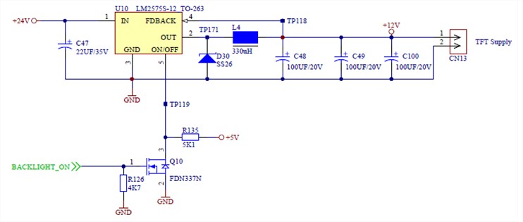
LM2575-12 fixed output buck converter with regulated 24V input

Input capacitor: 22uF 35V tantalum

Ouput capacitor: 3x 100uF 20V tantalum

Inductor: 330uH

We have few boards where one of the output capacitor burns out after 1min where 24V input is applied for the first time (without load). Any idea about possible root cause ?

Nick

  • With no load the output might overshoot.  Try to capture the output voltage waveform when you start under those conditions you mentioned.  What is the steady Vout when the cap is damaged ?

    FD

  • No overshoot observed with or without load.

    Steady Vout is 12V with less than 20mVpp ripple without load and 60mVpp with load.

    Without load, at pin 2 of LM2575, I can observe the following signal:

    Here's the schematics

  • I could be that The ESR of the caps is too high.  The ripple current may be overheating the cap.

    Try a diffierent cap with lower ESR or a 10-20uF ceramic in parallel.

    FD

  • Two other things about tantalum.

    1)

    At 50% voltage de-rating they have a failure rate of around 10PPM.  With a 20V part this doesn't seem to be the issue in your case.

    2)

    They also don't like to have large repetitive surge currents as they tend to overheat and fail.  Are these capacitors supplying large repetitive surge currents to the downstream equipment, or being short circuit tested?

  • Thanks for your comments.

    To Frank: The 3 capacitors used are given with a max ripple of 0.5Arms@100Khz (max ESR = 0.6ohm), it looks good for me regarding measured ripple ?

    To Marc: The fact is that 95% of failures happen the first time the board is powered for firmware loading after flying probe testing and the load is not yet connected.

    Any comments about the oscillation at pin 2 without load ? This oscillation is not observed when the load is connected (500mA for LED supply of TFT screen)

    Regards

    Nick

  • The ringing on the switch pin is normal for no load operation.  When the power switch is off and the diode current drops to zero, the switch node becomes high impedance and that node rings with the inductor and parasitic capacitance at that node.

    I can not think of anything that would damage the caps other than an overvoltage?

    FD