Hello,
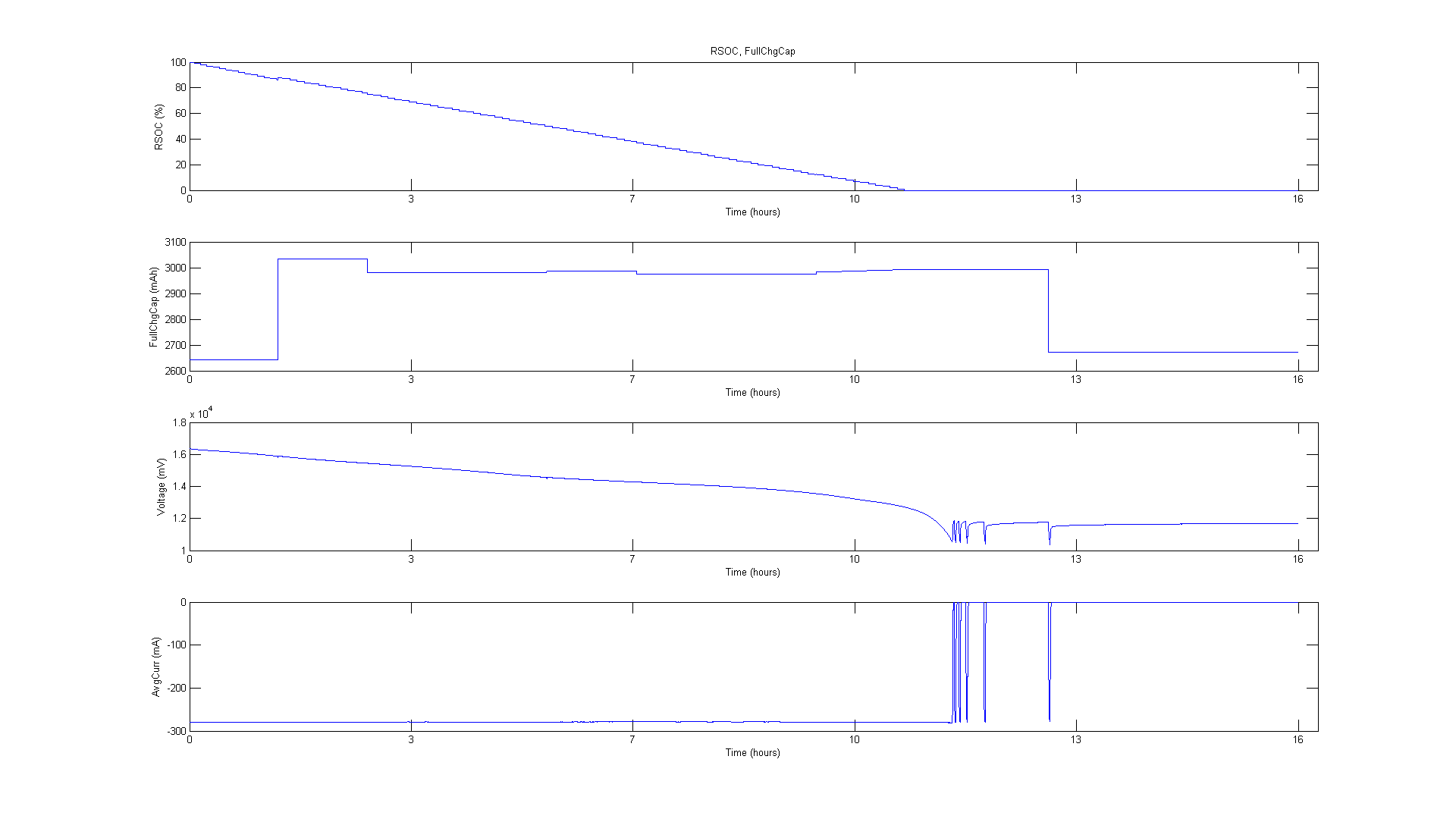
I'm having trouble with a 4 cell pack based around the bq20z95. Specifically, the FullChargeCapacity figure won't seem to settle. We have tested the cells with a battery analyser and found that the capacity is a little lower than stated in the datasheet - 3.1Ah (@3A down to 2.5V, vs. 3.35Ah), but I'm more concerned that the FCC value produced by the gauge won't seem to settle. Our application draws just under 300mA, so I would thought we would settle on around 3Ah.
As shown in the attached bmp, the FCC value does hit 3Ah for most of the discharge cycle, but after a full discharge, it seems to fall back 2.65Ah during relaxation.
Any suggestions on why this may be happening will be appreciated. Perhaps I need to repeat the learning cycle?
Thank you,
Jeremy.

[Header]
bq EVSW Version = 0.9.86
DeviceName = bq20z95 v1.50
Time = 4/11/2014 8:05:56 AM


[Voltage(1st Level Safety)]
COV Threshold = 4300
COV Time = 2
COV Recovery = 3900
COV Delta = 20
COV Temp. Hys = 10.0
POV Threshold = 17500
POV Time = 2
POV Recovery = 16000
CUV Threshold = 2500
CUV Time = 2
CUV Recovery = 2900
PUV Threshold = 10000
PUV Time = 2
PUV Recovery = 11600
[Current(1st Level Safety)]
OC (1st Tier) Chg = 2500
OC (1st Tier) Chg Time = 4
OC Chg Recovery = 200
OC (1st Tier) Dsg = 3350
OC (1st Tier) Dsg Time = 4
OC Dsg Recovery = 200
OC (2nd Tier) Chg = 3000
OC (2nd Tier) Chg Time = 2
OC (2nd Tier) Dsg = 3850
OC (2nd Tier) Dsg Time = 2
Current Recovery Time = 8
AFE OC Dsg = 03
AFE OC Dsg Time = 0F
AFE OC Dsg Recovery = 5
AFE SC Chg Cfg = 70
AFE SC Dsg Cfg = 70
AFE SC Recovery = 1
[Temperature(1st Level Safety)]
Over Temp Chg = 45.0
OT Chg Time = 2
OT Chg Recovery = 40.0
Over Temp Dsg = 60.0
OT Dsg Time = 2
OT Dsg Recovery = 55.0
[Host Comm(1st Level Safety)]
Host Watchdog Timeout = 0

[Voltage(2nd Level Safety)]
SOV Threshold = 18000
SOV Time = 5
Cell Imbalance Current = 5
Cell Imbalance Fail Voltage = 1000
Cell Imbalance Time = 5
Battery Rest Time = 1800
Min CIM-check voltage = 3000
PFIN Detect Time = 5
[Current(2nd Level Safety)]
SOC Chg = 6700
SOC Chg Time = 1
SOC Dsg = 13400
SOC Dsg Time = 1
[Temperature(2nd Level Safety)]
SOT Chg = 65.0
SOT Chg Time = 5
SOT Dsg = 75.0
SOT Dsg Time = 5
Open Thermistor = -33.3
Open Time = 0
[FET Verification(2nd Level Safety)]
FET Fail Limit = 20
FET Fail Time = 5
[AFE Verification(2nd Level Safety)]
AFE Check Time = 0
AFE Fail Limit = 10
AFE Fail Recovery Time = 20
AFE Init Retry Limit = 6
AFE Init Limit = 20
[Fuse Verification(2nd Level Safety)]
Fuse Fail Limit = 2
Fuse Fail Time = 0

[Charge Inhibit Cfg(Charge Control)]
Chg Inhibit Temp Low = 11.0
Chg Inhibit Temp High = 44.0
Temp Hys = 1.0
[Pre-Charge Cfg(Charge Control)]
Pre-chg Current = 256
Pre-chg Temp = 12.0
Pre-chg Voltage = 3000
Recovery Voltage = 3100
[Fast Charge Cfg(Charge Control)]
Fast Charge Current = 2304
Charging Voltage = 16800
Delta Temp = 5.0
Suspend Low Temp = 10.0
Suspend High Temp = 45.0
[Pulse Charge Cfg(Charge Control)]
Turn ON Voltage = 4150
Turn OFF Voltage = 4250
Max ON Pulse Time = 60.00
Min OFF Pulse Time = 0.00
Max OFF Voltage = 4270
[Termination Cfg.(Charge Control)]
Maintenance Current = 0
Taper Current = 128
Taper Voltage = 300
Current Taper Window = 40
TCA Set % = -1
TCA Clear % = 95
FC Set % = -1
FC Clear % = 98
[Cell Balancing Cfg(Charge Control)]
Min Cell Deviation = 1750
[Charging Faults(Charge Control)]
Over Charging Voltage = 500
Over Charging Volt Time = 2
Over Charging Current = 500
Over Charging Curr Time = 2
Over Charging Curr Recov = 100
Depleted Voltage = 10000
Depleted Voltage Time = 2
Depleted Recovery = 10500
Over Charge Capacity = 335
Over Charge Recovery = 2
FC-MTO = 10800
PC-MTO = 3600
Charge Fault Cfg = 00

[Data(SBS Configuration)]
Rem Cap Alarm = 335
Rem Energy Alarm = 4820
Rem Time Alarm = 10
Init Battery Mode = 0081
Design Voltage = 14400
Spec Info = 0031
Manuf Date = 01-Jul-2014
Ser. Num. = 0001
Cycle Count = 5
CC Threshold = 3015
CC % = 90
CF MaxError Limit = 100
Design Capacity = 3350
Design Energy = 48230
Manuf Name = TD
Device Name = bq20z95
Device Chemistry = LION
[Configuration(SBS Configuration)]
TDA Set % = 6
TDA Clear % = 8
FD Set % = 2
FD Clear % = 5
TDA Set Volt Threshold = 5000
TDA Set Volt Time = 5
TDA Clear Volt = 5500
FD Set Volt Threshold = 5000
FD Volt Time = 5
FD Clear Volt = 5500

[Manufacturer Data(System Data)]
Pack Lot Code = 0000
PCB Lot Code = 0000
Firmware Version = A41B
Hardware Revision = 0000
Cell Revision = 0000
[Manufacturer Info(System Data)]
Manuf. Info = 4S1P
[Lifetime Data(System Data)]
Lifetime Max Temp = 44.3
Lifetime Min Temp = 20.2
Lifetime Max Cell Voltage = 4175
Lifetime Min Cell Voltage = 1843
Lifetime Max Pack Voltage = 16681
Lifetime Min Pack Voltage = 8004
Lifetime Max Chg Current = 2253
Lifetime Max Dsg Current = -1980
Lifetime Max Chg Power = 36470
Lifetime Max Dsg Power = -26060
Life Max AvgDsg Cur = -2023
Life Max AvgDsg Pow = -2837
Lifetime Avg Temp = 23.7
[Lifetime Temp Samples(System Data)]
LT Temp Samples = 1967

[Registers(Configuration)]
Operation Cfg A = 2F29
Operation Cfg B = 6C48
Operation Cfg C = 0000
Permanent Fail Cfg = 0000
Non-Removable Cfg = 0000
[AFE(Configuration)]
AFE.State_CTL = 00

[LED Cfg(LED Support)]
LED Flash Rate = 2.000
LED Blink Rate = 1.000
LED Delay = 48.8
LED Hold Time = 4
CHG Flash Alarm = 10
CHG Thresh 1 = 0
CHG Thresh 2 = 20
CHG Thresh 3 = 40
CHG Thresh 4 = 60
CHG Thresh 5 = 80
DSG Flash Alarm = 10
DSG Thresh 1 = 0
DSG Thresh 2 = 20
DSG Thresh 3 = 40
DSG Thresh 4 = 60
DSG Thresh 5 = 80
Sink Current = 3

[Power(Power)]
Flash Update OK Voltage = 7500
Shutdown Voltage = 7000
Shutdown Time = 10
Cell Shutdown Voltage = 1750
Cell Shutdown Time = 10
Charger Present = 3000
Sleep Current = 10
Bus Low Time = 5
Cal Inhibit Temp Low = 5.0
Cal Inhibit Temp High = 45.0
Sleep Voltage Time = 5
Sleep Current Time = 20
Wake Current Reg = 00

[IT Cfg(Gas Gauging)]
Load Select = 1
Load Mode = 1
Term Voltage = 10000
User Rate-mA = 0
User Rate-mW = 0
Reserve Cap-mAh = 140
Reserve Cap-mWh = 0
[Current Thresholds(Gas Gauging)]
Dsg Current Threshold = 100
Chg Current Threshold = 50
Quit Current = 10
Dsg Relax Time = 1
Chg Relax Time = 60
[State(Gas Gauging)]
Qmax Cell 0 = 3324
Qmax Cell 1 = 3320
Qmax Cell 2 = 3320
Qmax Cell 3 = 3359
Qmax Pack = 3320
Update Status = 06
Avg I Last Run = -2023
Avg P Last Run = -2837
Delta Voltage = 0

[R_a0(Ra Table)]
Cell0 R_a flag = 0055
Cell0 R_a 0 = 221
Cell0 R_a 1 = 188
Cell0 R_a 2 = 183
Cell0 R_a 3 = 223
Cell0 R_a 4 = 228
Cell0 R_a 5 = 190
Cell0 R_a 6 = 221
Cell0 R_a 7 = 401
Cell0 R_a 8 = 412
Cell0 R_a 9 = 579
Cell0 R_a 10 = 1071
Cell0 R_a 11 = 1695
Cell0 R_a 12 = 2672
Cell0 R_a 13 = 3682
Cell0 R_a 14 = 4667
[R_a1(Ra Table)]
Cell1 R_a flag = 0055
Cell1 R_a 0 = 223
Cell1 R_a 1 = 190
Cell1 R_a 2 = 185
Cell1 R_a 3 = 226
Cell1 R_a 4 = 230
Cell1 R_a 5 = 194
Cell1 R_a 6 = 224
Cell1 R_a 7 = 405
Cell1 R_a 8 = 421
Cell1 R_a 9 = 591
Cell1 R_a 10 = 1103
Cell1 R_a 11 = 1796
Cell1 R_a 12 = 2907
Cell1 R_a 13 = 3990
Cell1 R_a 14 = 5059
[R_a2(Ra Table)]
Cell2 R_a flag = 0055
Cell2 R_a 0 = 221
Cell2 R_a 1 = 188
Cell2 R_a 2 = 183
Cell2 R_a 3 = 226
Cell2 R_a 4 = 233
Cell2 R_a 5 = 192
Cell2 R_a 6 = 226
Cell2 R_a 7 = 413
Cell2 R_a 8 = 429
Cell2 R_a 9 = 612
Cell2 R_a 10 = 1124
Cell2 R_a 11 = 1841
Cell2 R_a 12 = 2943
Cell2 R_a 13 = 4062
Cell2 R_a 14 = 5150
[R_a3(Ra Table)]
Cell3 R_a flag = 0055
Cell3 R_a 0 = 221
Cell3 R_a 1 = 188
Cell3 R_a 2 = 183
Cell3 R_a 3 = 226
Cell3 R_a 4 = 233
Cell3 R_a 5 = 192
Cell3 R_a 6 = 226
Cell3 R_a 7 = 409
Cell3 R_a 8 = 421
Cell3 R_a 9 = 600
Cell3 R_a 10 = 1103
Cell3 R_a 11 = 1811
Cell3 R_a 12 = 2834
Cell3 R_a 13 = 3827
Cell3 R_a 14 = 4852
[R_a0x(Ra Table)]
xCell0 R_a flag = FFFF
xCell0 R_a 0 = 329
xCell0 R_a 1 = 281
xCell0 R_a 2 = 273
xCell0 R_a 3 = 375
xCell0 R_a 4 = 362
xCell0 R_a 5 = 232
xCell0 R_a 6 = 288
xCell0 R_a 7 = 457
xCell0 R_a 8 = 471
xCell0 R_a 9 = 686
xCell0 R_a 10 = 1358
xCell0 R_a 11 = 2312
xCell0 R_a 12 = 3226
xCell0 R_a 13 = 4247
xCell0 R_a 14 = 5385
[R_a1x(Ra Table)]
xCell1 R_a flag = FFFF
xCell1 R_a 0 = 329
xCell1 R_a 1 = 281
xCell1 R_a 2 = 273
xCell1 R_a 3 = 375
xCell1 R_a 4 = 362
xCell1 R_a 5 = 232
xCell1 R_a 6 = 288
xCell1 R_a 7 = 457
xCell1 R_a 8 = 471
xCell1 R_a 9 = 686
xCell1 R_a 10 = 1358
xCell1 R_a 11 = 2312
xCell1 R_a 12 = 3226
xCell1 R_a 13 = 4247
xCell1 R_a 14 = 5385
[R_a2x(Ra Table)]
xCell2 R_a flag = FFFF
xCell2 R_a 0 = 329
xCell2 R_a 1 = 281
xCell2 R_a 2 = 273
xCell2 R_a 3 = 375
xCell2 R_a 4 = 362
xCell2 R_a 5 = 232
xCell2 R_a 6 = 288
xCell2 R_a 7 = 457
xCell2 R_a 8 = 471
xCell2 R_a 9 = 686
xCell2 R_a 10 = 1358
xCell2 R_a 11 = 2312
xCell2 R_a 12 = 3226
xCell2 R_a 13 = 4247
xCell2 R_a 14 = 5385
[R_a3x(Ra Table)]
xCell3 R_a flag = FFFF
xCell3 R_a 0 = 329
xCell3 R_a 1 = 281
xCell3 R_a 2 = 273
xCell3 R_a 3 = 375
xCell3 R_a 4 = 362
xCell3 R_a 5 = 232
xCell3 R_a 6 = 288
xCell3 R_a 7 = 457
xCell3 R_a 8 = 471
xCell3 R_a 9 = 686
xCell3 R_a 10 = 1358
xCell3 R_a 11 = 2312
xCell3 R_a 12 = 3226
xCell3 R_a 13 = 4247
xCell3 R_a 14 = 5385

[Device Status Data(PF Status)]
PF Flags 1 = 0000
Fuse Flag = 00
PF Voltage = 0
PF C4 Voltage = 0
PF C3 Voltage = 0
PF C2 Voltage = 0
PF C1 Voltage = 0
PF Current = 0
PF Temperature = 0.0
PF Batt Stat = 00
PF RC-mAh = 0
PF RC-10mWh = 0
PF Chg Status = 0000
PF Safety Status = 0000
PF Flags 2 = 0000
[AFE Regs(PF Status)]
AFE Status = 00
AFE Output = 00
AFE State = 00
AFE Function = 00
AFE Cell Select = 00
AFE OLV = 00
AFE OLT = 00
AFE SCC = 00
AFE SCD = 00

[Data(Calibration)]
CC Gain = 10.396
CC Delta = 10.396
Ref Voltage = 1224.60
AFE Pack Gain = 692.14
CC Offset = -0.245
Board Offset = -24.4
Int Temp Offset = 0.0
Ext1 Temp Offset = -1.0
Ext2 Temp Offset = 0.0
[Config(Calibration)]
CC Current = 3000
Voltage Signal = 16800
Temp Signal = 298.0
CC Offset Time = 250
ADC Offset Time = 32
CC Gain Time = 250
Voltage Time = 1984
Temperature Time = 32
Cal Mode Timeout = 300
[Temp Model(Calibration)]
Ext Coef 1 = -28285
Ext Coef 2 = 20848
Ext Coef 3 = -7537
Ext Coef 4 = 401.2
Ext Min AD = 0
Ext Max Temp = 401.2
Int Coef 1 = 0
Int Coef 2 = 0
Int Coef 3 = -11136
Int Coef 4 = 575.4
Int Min AD = 0
Int Max Temp = 575.4
[Current(Calibration)]
Filter = 239
Deadband = 3
CC Deadband = 10.0