This thread has been locked.

If you have a related question, please click the "Ask a related question" button in the top right corner. The newly created question will be automatically linked to this question.

TPS7A3501 Ripple Spike Rejection

Other Parts Discussed in Thread: TPS7A3501

Dear Sir,

I have a question how much TPS7A3501 can reduce Sipke noise came from DC/DC regulator ripple.

The PSRR (figure  13 in DS) shows until 10MHz which is good dB.  However spike noise possibly be around 100MHz zone.

Is tehere any perfromance information? And how much different comparing with ferrite bead?

Best regards,

Masa  

  • Hi Masa,

    The active power filter has rejects input noise up to around 1MHz, at which point the output capacitor rejects more of the input noise than the TPS7A3501. When dealing with ripple around 100MHz, you are out of the operational range of the TPS7A3501 and should focus on sizing your output capacitance to reject the ripple noise, or use another filtering method.

    Typically the most efficient way to deal with noise at those high frequencies is to first use an LDO or an active power filter to give you a low impedance DC supply that rejects the low frequency noise from a switcher and filters out most noise due to load transients on the switcher, and then size a few output capacitors to rejects the high frequency content.

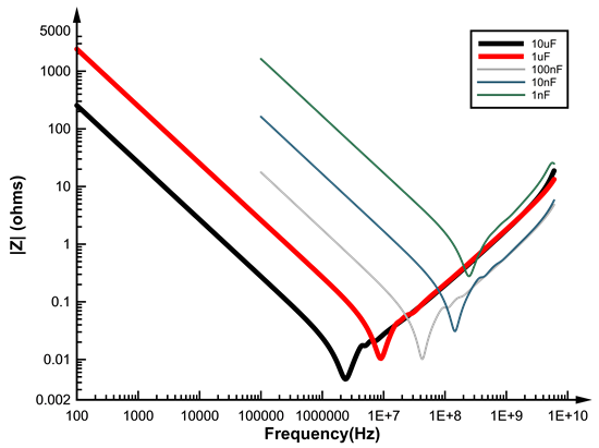
    Sizing the output capacitors is done through the impedance curves or the capacitors used. Most capacitor manufacturers will provide these curves. When picking the capacitors, your goal is to have your capacitor impedance as close to 0 as possible at the frequencies you want to reject. When you are doing this, try to stay on the left side of the resonant peak on the curve to ensure that you are still capacitive and not inductive at the desired frequency.

    Below is a plot of several impedance curves of different capacitors that shows how the peak shifts - the data was pulled some time ago from a capacitor manufacturers website:

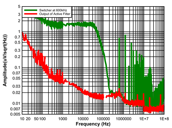
    Through this method you can significantly reduce high frequency noise. I utilized this method with the TPS7A3501 to produce the following spectrum, with the addition of 2 extra 0603 capacitors.

    Regards,

    David


  • Hi David,

    Thank you very much for your answer and data. I am very impressed that the noise specram at high frequency  (10M-100MHz) with TPS7A3501.  600KHz swuitching still makes high energy of harmonic noise at the band and the active filter can dramtically reduce. (Actually I comapre the noise at 10MHz with the figure 14 of TPS7A3501 datasheet.)

    May I ask questions; 

    what is capacitive value of two extra capacitors? (two 100nF?) ,

    were they addded parallel closer to 10uF Cout?

    And which Cnr is used on this specrum mesurment?  

    Best regards,

    Masa


  • Hi Masa,

    The output capacitors were all X7Rs: 10uF 0805, 100nF 0603, 10nF 0402. The 100nF and 10nF capacitors placed as close to the point of measurement as possible to replicate the location of real-world decoupling capacitors, so they were soldered onto the SMA connector from the signal pin to the ground shield. The 100nF and 10nF were also placed on the input side of the SMA connectors to keep EMI down, as when measuring a switcher EMI from the inductor can cause more spectral content than what is propagating through the devices. The Cnr was a 1uF, 0603, X7R.

    To reduce any EMI from the switcher, the EVMs for the TPS7A3501 were connected through SMA, as below:

    Regards,

    David

  • Hi David,

    Thank you very much for your perfect answer!!

    Best regards,

    Masa