Im using PMP4862 as a reference design for my thesis. I noticed that the schematics and the PCB dont match.
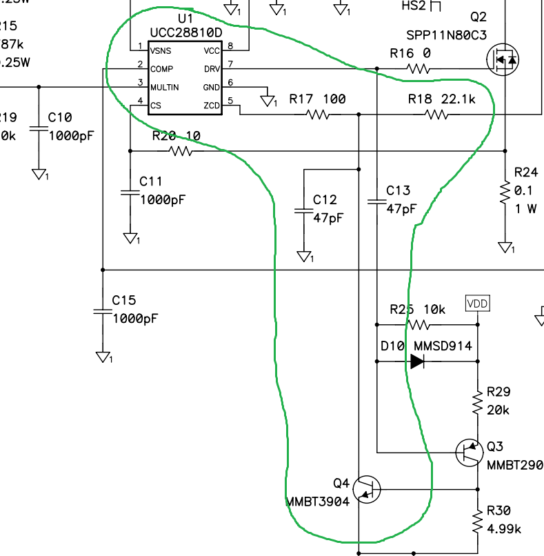
Im you take a look at these to images, at the PCB U1, R17 and Q4 are connected to each other. But on the schematics on the other hand, U1 is only connected to R17. Which one is correct? I want to make a PCB out ot this refernce but not sure which to follow.
http://www.ti.com/tool/pmp4862.1