This thread has been locked.

If you have a related question, please click the "Ask a related question" button in the top right corner. The newly created question will be automatically linked to this question.

TPS54331 stopped working properly

Other Parts Discussed in Thread: TPS54331

Hi,

I'm working on a circuit which has a TPS54331 working as a 24-5 volt regulator. It's been working like a charm for a long time, but then it suddenly stopped working properly. I changed all the components including TPS54331, but the problem still remains.

Well the problem is when I powered the regulator with a 24V input it I see a proper 5V on the output. But after a while output voltage drops and starts to wave as if it tries to reach 5 volts but can't.

I don't have an oscilloscope with me so I'm not able to see the signals. But I measure, I see +11V on PH pin, ~+4.3V on EN pin. When the output voltage drops these voltages drops as well.

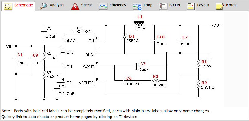
Here is my schematic with a little difference. My R1 resistor is 10.5K and R2 resistor is 2K

I replaced all the components several times but can't solve the problem. Hope you may point me a way to focus on.

Furkan.

  • Hi Furkan,

    I am not trying to be a wise guy here, :) but if you have changed out every part except the TPS54331, doesn't that mean you have a faulty TPS54331?

    Especially since most of the parts are inside the TPS54331? The data sheet says this device has an absolute maximum voltage rating of 30 Vs. You are operating at 24 Vs. Where is the source for the 24 Vs. Does it ever vary? Do you have input over-voltage protection?

    My guess is that a high input voltage broke the chip, or it's oscillating. Are you confident that your control loop has plenty of phase and gain margin? 

    If your converter is conditionally stable it will perform in the manner you describe. If you only have a few degrees of  phase or gain margin and something gets too hot and changes value, you can start oscillating.

    Chuck


  • When you say the circuit was working properly for a long time, how long is "long"?  Hours?  Days?  Years?  You say you replaced all the components?  If so that should have fixed it, since it worked properly before.  Did you change the load?  I suppose we will need to see waveforms to diagnose this.

  • Hi Chuck,

    Thanks for the answer.

    I've already replace TPS54331.  I believe my 24 volt source is pretty acceptable,  I use a good quality smps. But you are right, I should look at input voltage with an oscilloscope.

    Hi John,

    Thanks for the answer.

    The regulator is a part of an embedded system that I've been designing for quite some time. It has been working the last two weeks, nearly 6-8 hours a day. The problem occurred after I moved it to home from office. So I thought it could be a capacitor problem. But changing caps didn't work. I didn't change the load.

    I know it's hard to say anything from there :). 

  • Hi, 

    I made a new clean PCB for the same regulator circuit. This time I could get a clean 5 volt output. But when I add some load about a few mA, the output voltage falls. When the load is about 40-45 mA the output voltage is approximately 3.3 volts. 

    Does this mean there is something wrong with C6,C7,R3 on the schematic?

    Furkan.

  • Can you post your inputs to switcherpro?  Did you modify any of the components or use exactly the output that switcherpro produced.  let me know and I will try to re-create it.

  • My input parameters are   VinMin=20V, VinMax=28V, Vout=5V, Iout=3A .

    I tried to use the same components that switcher pro advised with one exception. For Vsense voltage divider, the circuit says 10k and 1.87k; but I use 10.5k and 2 k. I calculated this two resistors by using the equation shown in data sheet.