This thread has been locked.

If you have a related question, please click the "Ask a related question" button in the top right corner. The newly created question will be automatically linked to this question.

LP5907 – About the accurate package dimensions.

Guru 21045 points
Other Parts Discussed in Thread: LP5907

Hi Team,


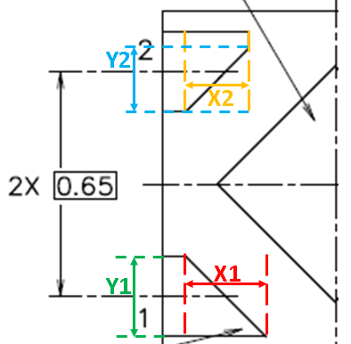
Could you please let us know the accurate package dimensions(X1 and Y1 (PIN1) , X2 and Y2(PIN2,3,4))?

Our customer needs this information to design it.
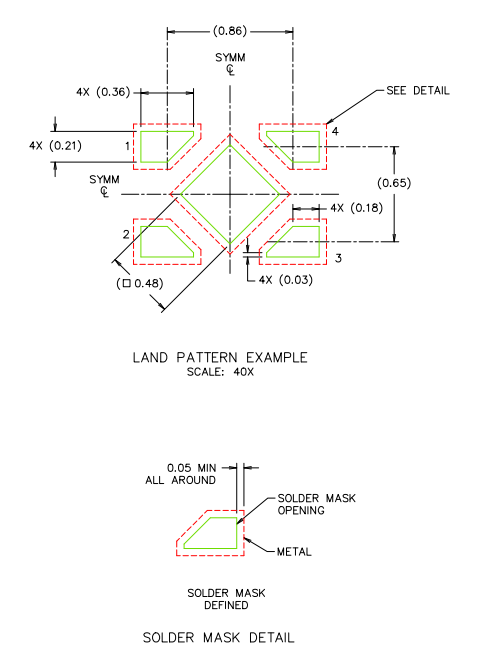
 

<package dimensions>

X1 = ??mm +/- ??mm

X2 = ??mm +/- ??mm

Y1 = ??mm +/- ??mm

Y2 = ??mm +/- ??mm


I’d greatly appreciate your verification.


Regards,

Kanemaru

  • Your question has been forwared to the Packaging team.

    They should have an answer for you shortly.

  • Hi Donald-san,


    Thank you for your response!

    I’m looking forward to hearing from you.


    Regards,

    Kanemaru

  • I am not a package expert, but it seems to me that the existing X2SON Solder Mask Detail page should provide enough detail to determine the dimensions being requested.

  • As Don has responded, the recommended footprint has been developed and tested to properly balance the solder with the package, as well as do eliminate the acute corner that pin 1 would require by making all pads the same. It is recommended that customers do not deviate from the land pattern example above.

    SolderMask Defined (SMD) pad definition is recommended so that PCB trace connections do not disturb the requirements for proper balanced assembly. There should be no need to define a different type of footprint.

  • Hi Donald-san, Ernesto-san,


    Thank you for your advice.

    I understood a recommended layout.

    However, our customer needs the accurate package dimensions(X1 and Y1 (PIN1) , X2 and Y2(PIN2,3,4)).

    Because, they must prepare the macro model of LP5907 for board implementation.

    So, if this goes on, they can’t design it if there is no information.

    Therefore, We would like to know this information.

    Could you please let us know it?


    I’d greatly appreciate your verification.


    Regards,

    Kanemaru

  • Kanemaru-san,

    If I interpret your response correctly, the customer appears to want to build a mechanical model for the part. You can go ahead and pass on the two files contained within the attached ZIP file to the customer.

    0576.DQN0004A Mechanical Models.zip

    It contains:
    DQN0004A.stp - 3D mechanical model in STEP format. Most PCB CAD layout systems will use this format to display and manipulate the component in 3D space.
    DQN0004A_3Dint.pdf - 3D PDF of the above. The 3D PDF file may require user to click twice on the blue cube button named "Use Perspective Projection" to eliminate a bug in the PDF display.

    Best regards,  Ernesto.

  • Hi Ernesto-san,


    I greatly appreciate your cooperation!!

    We will report the information to our customer.


    Regards,

    Kanemaru