This thread has been locked.

If you have a related question, please click the "Ask a related question" button in the top right corner. The newly created question will be automatically linked to this question.

LM5085 Frequency Stability

Other Parts Discussed in Thread: LM5085

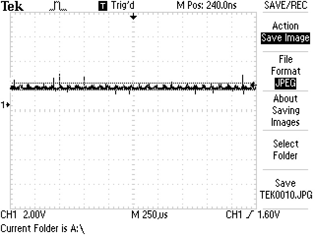
The SW Node pulse seem to increase/decrease in time and at some voltages are not stable.  For example, I can trigger on a specific pulse and it centers the image in my o-scope.  The pulse ahead and behind seem to jiggle back and forth.  This doesn't happen at all input voltages.

Has anyone noticed this and what did you do to stabilize the switching frequency?

Thanks,

Seth

  • Can you post your schematic and some waveforms that demonstrate your concern?

  • Hi Seth,

    As John said, including some images will be helpful. Schematic will help as well.

    The jitter in this part is related to the amount of ripple. Smaller ripple at FB node can cause more jitter. The LM5085 datasheet has 3 ripple methods discussed to stabilize the switching waveform.

    Regards,

    Vijay

  • I think I've found the issue.  There is no "R4" in front of Cout.  Thus, I get squirrely results at the low input voltage range.  I appreciate the suggestions guys and forgive me for posting before I had done enough research.

    Thanks!

    Seth

  • I've take an look at this tonight and I'm getting a lot of noise in my feedback path.  Also, the ripple voltage looks high at around 800mV at Cout which translates to nearly 1/2 a volt after feedback scaling. 

    Attached are the output plots from the O-Scope. I have the simple ripple circuit where Cff is 1.5nF and Cout is 47.0uF.  I'm using the alternate Output Ripple Configuration (section 8.2.2.2) from the datasheet, page 19 without the R4 inline capacitor with Cout.

    Also, on the next layout, I've isolated the feed back path with a ground plane in between the feedback path and the SW node.  Should help a ton!

    For R4, I've calculated around 0.0625Ohms which seems too small.  The capacitor that I'm using for Cout has an ESR of 500mOhms.  So, not sure that an R4 would do much difference.  If I purchased a cap with a smaller ESR, that would effectively reduce the ripple voltage, correct?

    The below ripple voltage plots were captures at 1A output.

    Thanks,

    Seth

  • Hi Seth,

    The first waveform looks very clean. Also it has no oscillation going on. Not clear what the second waveform is.

  • The ripple voltage at FB usually does not need to be that high.  25mV or so is usually sufficient.