I am just starting to use a BQ27510EVM. Do I need to connect a charger or a power supply and a fresh discharged battery for it tto start the learning cycle?
This thread has been locked.
If you have a related question, please click the "Ask a related question" button in the top right corner. The newly created question will be automatically linked to this question.
I am just starting to use a BQ27510EVM. Do I need to connect a charger or a power supply and a fresh discharged battery for it tto start the learning cycle?
I'm assuming you have completed the prior steps in bqEASY before reaching step 5 (Learning Cycle).
At this point you must be using the actual cell that you plan to use in production.
You must also have identified the best ChemID match to your cell in step 4 of bqEASY and programmed the corresponding default chemistry values into your IC.
Then your cell must be discharged AND relaxed (let it sit for at least 5 hours).
Then (continuing to follow the procedure outlined in bqEASY step 5) you will enable IT (click the button, or send command 0x21 to the Control() register).
Then you will start charging, either with your actual charger or with a power supply set to 4.2V and with the current limited to about C/2.
Once the charging is complete (and the gauge shows the FC bit is set/red on the DataRAM screen), let the cell relax for at least 2 hours.
Confirm that Update Status (Data Flash screen, Gas Gauging tab) has changed from 0 to 1.
Now you can begin your discharge at about C/5. Be sure to stop the discharge at some point below your terminate voltage. Do NOT discharge your battery to 0V (that will destroy your battery). Do NOT discharge your battery so low that the gauge shuts down. Discharge to no lower than 2.8V, then shut off the load and allow the battery to relax at least 5 hours. At some point during the relaxation, Update Status should change from 1 to 2. Assuming you get this to happen, your learning cycle has been successful.
Did your eval kit include an EV2300 (USB-I2C box)?
First you must plug it in to your PC and allow the drivers to be installed. It will install TWO drivers and you might have to interact with the dialogues to get them installed. If you plug the EV2300 into another USB port, it will need to install the drivers again for that port. Anytime you plug it into a new USB port, it will need to install the drivers, FYI.
However, once you have the drivers installed, you can start the bq Evaluation Software. If it finds an EV2300 plugged in, it will hook into it. If there is a powered EVM plugged into the EV2300, it will query it for the device and firmware version. If you have installed that version of EVSW, it will automatically launch. If you don't have that version or there is no EVM or EV2300 plugged in, it will pop up the dialogue box where you can select your device and version. If you pick one and continue, but it can't find a gauge to talk to, it will give you the message you just saw.
So...
First plug in the EV2300 to your PC by USB and make sure the drivers are installed.
Second, connect the I2C port of the EV2300 to the I2C connector on your bq27510EVM.
Third, apply 3-4.2V across the Pack+ and Pack- connectors on the bq27510EVM.
Fourth, start your bq Evaluation Software (EVSW).
If this is what you did and you still got the error, let me know.
I just went through the whole process again and noted down the points that I did, and they are exactly the way that you have told. I downloaded and run the BQeval uation file, and then connected the EV2300, it then asks for the drivers, so run the drivers(2 of them)..and everything like hw u said, Still it gives me the same message. AFter that,I tried probing the REG25 pin,jus to see if the IC is getting powered, and I found it does. After this I opened the eval software, and it gave a different message this time around:" device incompatible..... continue at ur own risk""..i clicked ok..thn i checked the I2C lines..and there is nothing on it?? Would the IC hv gone offf?
could somebody please give some suggestions as to waht needs to be done!
It sounds like your communication is fine but you have a different version of firmware in your IC than the version of EVSW that you are running.
Despite the warning message, go ahead and click "Refresh" on the DataRAM screen. It should read a bunch of registers and they should turn color on your screen instead of gray if the reading is successful. Give me a screenshot of this. The top bar of the window will show the firmware version that EVSW is expecting. The bottom bar of the window will show the version actually read from the IC. Did you upgrade to bq27510-G1 (v1.12) yet?
When you say there is nothing on the I2C lines, do you mean there is no voltage as measured with a voltmeter, or there are no waveforms as measured by an oscilloscope? If you are not actively communicating with the IC (by clicking Refresh, for example) then the lines will be low.
Regarding the I2C lines, they are high when the board is powered, and when ths software is enabled, it goes low. Hence,I never saw any voltage on the line. BUt, when I refresh, it goes high and it does toggle everytime I refresh. THe other thing now,is thatI have to click on refresh manually for the software to update the readings, Is it normally like that or is it because of the firmware ver problem or is it yet another problem?
You need to upgrade the IC first by following the instructions in SLUA453A:
Updating Firmware with the bq2750x and EVM (Rev. A)
You will use the SENC file in the Tools & Software section of the bq27510-G1 Product Folder on ti.com:
Skip straight to page 5 if you don't need to save any of your current data flash settings.
After upgrading, you will need to re-calibrate since those values will be wiped out.
It is normal to click Refresh to update the values on the DataRAM screen, unless you have checked the Keep Scanning box. You can change the scan rate in the Options menu. You can also selectively scan only certain commands/registers by making sure only the desired ones have checks in the boxes next to them in the Scan column.
HI David,
Thanks for your response.I am working on your sugestion. Meanwhile do you think its necessary for me to recalibrate? Because,I havent started connecting it to a bateryso far.If this works, it will be the first time, I get to work properly with the Eval module adn software.
Great!
Yes, go through bqEASY step-by-step and you should be fine.
However, on the calibration step it is best to use an external power supply in place of the battery since you will use a 1A load for calibrating the current reading.
I usually just use an external supply up until I'm ready to do step 4 (Chemistry selection) and step 5 (Cycling for learning).
Hi David,
I have a few more queries ...COuld you please help me!
1)It says the default .dfi file bq....0_00 was not found,instead can I use a bq27510_1_11.dfi to start with?
2)My battey chemistry is not found on the list.What should be done?-click on Enable cycling, and how does the data generated be used?
3)FOr Chemistry cycling, I shud connect the battery and use the circuit diagram as mentioned?
4)When you say charge to C/100 taper current,.what does it imply?.(Normally we just charge it to 1A)?
5)And, should the charging done with eval board connected(via the charger pins on the board)or using a power supply with the eval board not connected( Like hw we normaly charge?)
1) NO, do not use a 1.11 DFI with 1.12 firmware. If you did a fresh SENC load on your IC, then click "Keep Existing Dataflash Image" and continue. If you ever have to start bqEASY again and the DFI is missing, just program the SENC again. It will reprogram your dataflash and instruction flash. (The DFI will only program the dataflash.)
2) Yes, if your cell is not on the list in 4B, continue to 4C.
3) Yes, use the attached circuit (you need an extra FET or relay in series with your load and controlled by the HDQ:VOUT pin on the EV2300). Test your circuit with the Test it... buttons. This will enable the EVSW to cut off the load when the voltage drops to your terminate voltage after you click Start Test.
4) Charge to C/100 taper current means that if your cell has a capacity of C=1000mAh, you should charge it to 4.2V AND stop when the current reduces to C/100=10mA or less.
5) You can charge the battery separately or through the Charger pins on the EVM, but it is simplest to just use the EVM pins instead of disconnecting your battery.
When you say:" Yes, use the attached circuit (you need an extra FET or relay in series with your load and controlled by the HDQ:VOUT pin on the EV2300). Test your circuit with the Test it... buttons. This will enable the EVSW to cut off the load when the voltage drops to your terminate voltage after you click Start Test."
So,does that mean that I have got to keep the I2C bus connected, connect the circuit between the "HDQ pins of the EV2300 " and "Load+ and Load -" on the BQ27510EVM?
Hi David,
To do the chemistry cycling, I need to use a low voltage MOSFET. But hwo low should Vgs threshold be--- is it 4.2V ??Can I use SI1012?And, for the resistor, the current is my battery rating –right? So, if I were to use a battery of 4.2V,1800mAH, then my R value will be a 10ohms ,1.5watt?And and that inturn should be connected to the EVM?
Could you also please reply the prev query.
Thanks .
1.8V should be low enough.
For the resistor, you should size it to draw C/5 for chemistry identification, so you are correct:
If you use this as your load it will maintain an acceptably stable current for the discharge.
The FET will be in series with this load and will be cut off by the EVSW when the voltage reaches your terminate voltage. This is to avoid discharging your battery too low and damaging the cell. The other option is for you to watch the voltage and cut it off by hand at the right time, or use some other method to stop the discharge automatically.
You leave the I2C port connected to your EVM for communication, then connect additional wires from the HDQ port. HDQ:GND will go to the source of your FET and common ground. HDQ:VOUT will go to the gate of your FET. You can see the circuit in a larger view by clicking on the little picture in step 4C of bqEASY.
Hi David,
When I dint find your reply, I did tryto do the test in teh way that the BQEASY guided me through.It was 7 steps in all,but my battery seemed to have died before the steps completed. Could it be because of the load(not a constant current), which could have drained my battery.And.the other thing is I dont know what to with the data that I got to build a chem file from it,since we do not have MATHCAD here.
Regards,
SA.
It sounds like your circuit did not shut off the current before the battery was too deeply discharged. You should start with a new battery for the optimization (learning) cycle in step 5.
But first, we need to identify your battery chemistry. If you click the "Match Best Chemistry" button in step 4C it should identify the best ID based on your discharge data. Alternatively, you can send me the log file and I can run it through Mathcad for you to find a fit. Send me a friend request and you can get me the file.
David,
I am having the same version problems as addressed before, except when I try to follow the SLUA453A instructions for upgrading the firmware to 1.12 , the bq27510 seems to not respond at all. not to DataRAM or I2C Pro actions. I get the "Failed Read Data with (decimal) error code : 772" dialog message. Looking at the EVM board itself, the chip is powered and the 2.5V Regulated out is OK. Is there any recovery to this or is this terminal for the chip ?
Hi,
As far as my problem was concerned, I just needed to reload the new firmware onto BQ27510, and I dint have to save the flash contents. If thats your situation as well, then I suggest:
1) Hope you have had the drivers installed properly
2) Have up-to-date versions of the BQ sw and .senc file.
3) Once you are done with this, connect your EVM(powered by your battery or 4.2 power supply) via EV2300.
4) Click Refresh on screen.Does it respond? IF it does, then open the software and follow the instructions on Page 5 of SLU453.A.
Thanks David. I shall wait for the results. Meanwhile,il just try to find out why my circuit did not cut off the current , and not let my battery to be highly discharged.I hve been thinkin of switchin ON/OFF the ciruit manually, but the fact is, if the chem test is not automated, the software jus keeps running,irrespective of the state of hardware.
Hi David,
Liek, How I discussed earlier, Im tryin to do the chemistry cycling again.However, this time when I reach step 2, I get the BQEASY to say "disharge from 100-60%", and RSOC =100.15, 100.20, 100.74 and so on..somethihg wrong..it seems to be counting up..rather than down..> or is it jus a software bug?
Can you post a screenshot of the error you are seeing? I'm not familiar with your description.
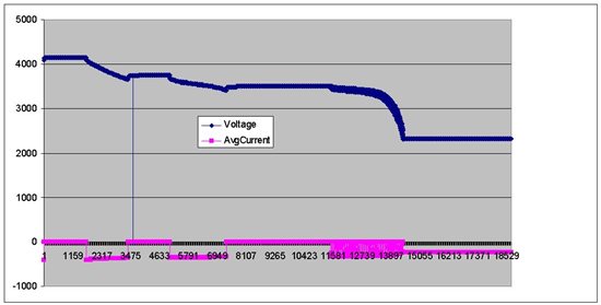
I just plotted the Voltage and AverageCurrent from your log file and it looks very strange. I inserted the plot below.
What we need is a continuous discharge from 4.2V to about 2.8V to identify the proper chemistry ID for your cell. Unfortunately this log shows a discharge to 3.7V, then relaxation, then discharge to 3.4V, then relaxation, then an intermittent discharge until it reaches about 2.3V. This cell is probably damaged now.
I'm not sure what is going on with your FET/relay circuit, but maybe you should just remove it, begin the logging, and start a discharge from full to around 2.8V that you stop manually. If you get a smooth discharge curve then send me that log and I will identify the chemistry for you.
I'm sorry this is turning out to be such trouble for you, but let's keep trying and we'll get it figured out!
Hi David,
After reading your post, I have a feelein if I am doing something wrong. But, I have definitely followed exxactly the way BQEASY takes me through. The way, I do is: connect the discharge circuitry to load, and battery to battery terminals. I then do step 1 to step3 of BQEASY, and for step4:I do the following: enable chemistry selection---> Cant identify chemistry --->Test it ON ---> Charge done ---> start test.
Once I start the test, it goes through 7 phases or 7 steps. If I remember it right, it is:
Step | Charge/discharge | Remaining Voltage displayed on BQEASY |
1 | Relax charge for 2 hours | 4.15V |
2 | Discharge from 100% to 60% at C/10 | 3.7V |
3 | Wiat 2 hours for discharge from 100% to 60% to relax | 3.6V |
4 | Discharge 60% to 10% | Not noticed |
6 | Pulse Discharge from 10 % to 2150 V |
Battery drained |
Note:
1) I dont know what step 5 was...
2) Step 7 could not be reached since my battery had already been drained .
3) I have attached images for the Step1, Step4 and Step6 with their respective steps as file names.
That was how my first Chemistry cycling test looked like, and the log file of which I have sent to you. So, I presume, what you see in the log cycle as intermittent charge ,relaxation and discharge cycles are as controlled by the BQEASY software itself which is how I have done.
However, after having sent you the log file, I decided to use a relay instead of a FET, and thats when I got that error stated in the previous mail. I dont know if I should call it a a error. The problem was in STEP2---- Instead of discharge from 100% to 60% it used to go Discharge from 100% to 100.1%, 100.2% and so on... and RSOC was rising from 4.2V to 4.21 , 4.22..and so on... I assume, this could be a problem of my circuit. I shall attach the image under the name "error_chem cycle2".
I thank for your pateince as well, in helping me sort my problem even if I havent got anywhere with it. Because, I tried contacting the support team at epic@ti.com and response seems to be very upsetting. The team/person used to respond immediately until I purchased the kit and there has been little or no repsonse ever since. I have not beeen able to demonstrate any postive results with this kit in the last 1.5 months which pulls down me a lot. However,like how you say, I hope to get it sorted soon and get it up and running with the rest of my project.
Thanks and Regards,
SA.
The pics for step1, step4, step6 and error-chem_cycle 2 are attached as below.
Hi David,
Now, can I do the test with just a 10ohm resistor( as load) and jus log the values without using the BQEASY chemistry cycling at all?Is that what you have meant by saying dropdown the voltage from 4.2 to 2.8V ?Or do you think I should still configure all the parameters in BQ EASY?
Thanks and Regards,
SA
Here are some things you can try:
- be sure you have the latest EVSW installed. We just released a new version for all the single-cell gauges, so go here and install the new bqEV-EASY.
- be sure you have closed the Calibrate sub-window inside EVSW before you try go to Step 4 (chemistry identification)
However, I don't want to ask you to try again to use the wizard for chemistry ID. Let's forget about using step 4C to automate the process.
Your log was correct for using step 4C, but it doesn't work for using the Mathcad worksheet which is want I want to do.
Now just use your resistor load (use a C/10 discharge rate) and discharge from 4.2V to 2.8V with a continuous discharge while logging the RAM.
Upload your log file and I'll use that data in the Mathcad worksheet to identify your chemistry.
FYI, if you have Mathcad yourself you can use the tool:
http://www.ti.com/litv/zip/sluc138h
Hi David,
I have been tryin to discharge a fresh battery at C/10 rate but it seems to take more longer than 9 hours,so..il have to redo before I stop it at the end of my working day. Since. I have had to redo the test, I just wanted to know if I can use a once dishcarged n charged battery for this chemistry cycling test.
We do not have Mathcad installed,so, I shall send the log file to you, once I am done with it.
Thanks and Regards,
SA.
HI David,
I have attached the log file for my battery. Could you please have a look .
Thanks and Regards,
SA
Hi Ming,
I have just noticed that you have verified some of the posts... but , the thing that I am waiting for is: To dientify my battery chemistry from the attached log file. Will you be able to help me with it?
the post is posted on 24Apr 2010 and it has got a log file of my battery attached.
Thanks and Regards,
SA
I tried to analyze your log file but it was not successful. Please re-take the data but follow these more detailed instructions:
- set log interval to 5 seconds (not 1 second)
- charge battery to full (4.2V) with CC/CV method and stop charging when current is < C/100 (you can use a power supply for this)
- allow battery to relax for 2 hours
-start the EVSW log before you begin the discharge
- begin discharge at ~C/10 rate to 2.7V (if your battery protector will open at a higher voltage, then stop before you reach your protector cut-off voltage. 2.8V or 2.9V is also okay, but 2.7V is ideal to get the maximum data.)
- after you reach terminate voltage on the discharge, shut off the load and allow the cell to relax for 5 hours. Continue to log for these 5 hours.
- After 5 hours of relaxation, you can stop the log and post it again for me to analyze.
The relaxation data is also an important part of the chemID matching process and it wasn't included in your original log. I'm sorry I didn't mention it earlier.
Best regards,
David
http://e2e.ti.com/cfs-file.ashx/__key/CommunityServer.Discussions.Components.Files/180/8054.batt_5F00_07_2D00_05.log:550:0</p> <p>Hi David,
The log file for my battery is attached. I had to wait for the weekend to get a full16 hr control over the battery test.Hope this data is right.
Thanks and regards,
SA.
Hi SA,
There were some discontinuities in your log file but I fixed them and finally got a good ChemID match for you.
It looks like chemID 227 is the closest for you to use. Please choose 227 in bqEASY to program into your dataflash, then perform the learning cycle to create a golden image.
I also calculated the optimized Ra table from your data. After your learning cycle your Ra table should be similar to the one in the attached partial GG file. You can take the Ra table, use the decompression formula on page 5 of SLUA450 and plot it in Excel. Plot the one from your learned data and the one from my file. They should be similar.
I hope your learning cycle goes smoothly. Please let us know if you have any problems creating your golden image.