This thread has been locked.

If you have a related question, please click the "Ask a related question" button in the top right corner. The newly created question will be automatically linked to this question.

BQ20Z45-R1 Sleep Mode Timing

Other Parts Discussed in Thread: BQ20Z45-R1, BQ20Z40, BQ20Z45

Hi,

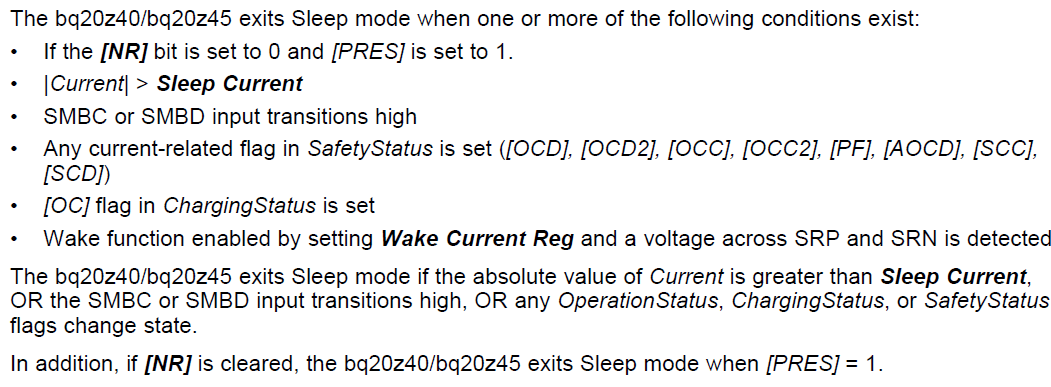
I am using the BQ20Z45-R1 and would like to reduce the average sleep mode current.  When the BQ20Z45-R1 enters sleep mode I measure the expected 50uA supply current. 

The IC then appears to wake-up at approximately 1 second intervals drawing 400 to 500 uA.  Every 5 seconds or so, the current increases to > 1000uA.  The effect of these wake-up events is an average sleep current of 120uA.

The wake-up intervals appear to be 4x to 5x faster than the intervals given in the BQ20Z45-R1 data sheet and reference manual.  Is there a setting that I can use to adjust the wake-up intervals?


Thank You!

Doug Young

  • Well as you imply the TRM clearly says 

    " In Sleep mode, the bq20z40/bq20z45 measures Voltage and Temperature at 5 s intervals and Current  at 20 s intervals."


    As far a I know those times are not programmable but even if they were the bigger concern is that your gauge seems to be ignoring them and waking at 1 second intervals and not 5 second which begs the question why? I am wondering whether something else is actually waking the gauge ?

    Per TRM

    So you should check that none of these conditions might exist.

    The sleep current is 10mA by default and I am wondering did you change that?  What is any load across the battery doing while it is asleep, could any activity on the load side be waking the gauge at 1 second intervals? Is the system host micro waking and causing the battery to wake ?  If sleep current is still 10mA then I would not expect a load side 500uA draw to wake it unless there is also some kind of initial large current spike as well waking it . Is this a removable or non removable gauge , are you trying to charge  while asleep ?  Lastly what are the SMBC and SMBD lines doing, could they be tranistioning high to wake it ? 

  • Hi Mike,

    Those are good questions to clarify the circuit setup and as you stated, the problem is that the gauge appears to be waking at intervals faster than those specified in the TRM.

    My test circuit for the BQ20Z45 is very close to the BQ20Z45 evaluation board, and I see the same behavior in the EV board after writing my .gg file to its BQ20Z45.

    The charge and discharge FETs are shutoff and I have tested with sleep current values of 100mA and 10mA.  The meter I am using to measure current also stores max current reading and this has been about 1.5mA so it seems unlikely the BQ20Z45 is being woken by current.  Even if it was woken, I expect that it would stay 'awake' for about 1 min. before going back to sleep mode, and this is definitely not happening.

    The gauge is removable but the PRES# line is pulled to REG25 during the test and is not being pulled low.  Again the gauge would wake for 1 minute if PRES# was pulled low.

    The pack is not being charged.

    The SMBC and SMBD lines are pulled low through 1M Ohm resistors during the test.  External communications devices have been disconnected.

  • Doug,

    Is this a pack gauge you developed yourself or one that you have bought from a 3rd party. It might be possible that pack developer altered the default 5 and 20 seconds settings for some reason. Are you able to extract a senc file from the gauge and send it to me ? See section 3 of http://www.ti.com/lit/an/slua474/slua474.pdf for how to do that. I can then at least check what the gauge thinks it is doing.

    One way to see if the part is really waking is to check the Thermistor supply line to see when it wakes up .If you monitor TOUT you should see it power the thermistors when the parts wakes.

    Mike


  • Mike,

    The pack and gas gauge / charge circuit are all developed in-house by Microprocessor Designs.  The gauge is executing the factory FW, version 105.  I have attached a .zip file that contains the .senc file exported from the gauge, a log to show the flag settings and a .png capture of the TOUT o'scope trace.

    In the TOUT trace there appears to be an event that is powering TOUT for about 2msec with an approx. 250msec period.  TOUT is powered for 40msec on a 5 sec. period. 

    Interestingly TOUT is not powered at the 250msec interval just before the longer 5 sec. power pulse.  Instead there are two short TOUT power pulses at the 250msec interval following the 5 sec. power pulse.

    Doug

    BQ20Z45_ShortSleepInterval.zip
  • Mike,

    FYI - It appears that there is an error in SLUA474 section 3, step 6 which reads:

    "6. In the Send SMB Command area set the SMB Command box to 00 and click the ‘Send’ button. This
    will restart the firmware"

    I had no success issuing SMB Command 00 to restart the FW.  Fortunately I had viewed one of the TI videos and noted that SMB Command 08 is sent to force the gauge out of ROM boot mode.  Command 08 was successful for my BQ20Z45-R1 gauge.

    Doug

  • Doug,

    well caught on the 00. That app note only recently came more to my attention and it looked well written at first sight , especially since they show 08 loaded in both the two pro screen images in that section ( although not that specific point) so I missed the erroneous 00 in the text for that point. I thought I could speed up and stream line my reply, avoiding having to do my own long wordy 'how to' description by simply refering to the app note but clearly not.

    I'll take a look at the zip and get back to you.

    Mike

  • Doug,

    I have been playing with your senc on my EVM. Could you confirm what the normal operating voltage range is for your cells? You have overvoltage thresholds relatively low , ie COV is 3700 and SOV is 3800 yet you are using the 0100 CHEM ID which suggests a cell that goes much higher. So straight off with my cells set arbitarily around a nominal 3800V I was getting a SOV PF from a cell that was above 3800. If you have an active  PF it will stop you going into sleep mode which I wonder is what the scope shot is telling us. eg You are actually not asleep ?  Can you double check if you have any active PF flags , if you have check relevant fail conditions you intend and/or remove the error condition , and send the PF clear key to remove the active PF then try your sleep experiments again?    Note -  I don't see any stored PF flags so maybe I am wrong that a PF could be preventing sleep mode?

    In cfg A you have the cc0 and cc1 bits set which says to me 4 cells is that what you actually have ?  I also see design voltage is 12800 which says nominally 3200 per cell if it is 4 cells . I guess that is consistent with the COV and SOV thresholds and if it was 3 cells that would be 4267 per cell which would be too high. Just trying to second guess the issue here.

    I note that update status is 04 so this gauge has not done a successful learning cycle to update Qmax and ra Values. I am not aware of any requirement to do a learning before you can activate sleep mode but I can look into that.

    The sleep mode time settings are configured to the default factory 5s and 20s settings described in TRM ,

    Mike


  • Mike,

    The pack is 4 cells in series, LiFePO4 chemistry, 2V to 3.65V per cell, 1500mAh capacity (AA Portable LFp-18650-1500).  Sorry for the confusion as I forgot to update the chemistry after doing a gauge IC replacement on the PCBA.

    I do not see any PF flags set in the PF status register or saved PF flags data flash values. 

    I did try the following with no effect:

    1. load the correct chemistry.
    2. load the .senc file for revision 1.105 build 0005
    3. load the correct chemistry
    4. test sleep mode (no change in TOUT timing)
    5. change the gas gauge update status to 02 in the .gg file and reload.
    6. test sleep mode (no change in TOUT timing).

    In my experience, if there is a PF flag set or the PRES# pin is not set correctly, the gauge will not drop to a 50uA current mode.  This suggests to me that when my meter measures a periodic 50uA battery current that the gauge is going to sleep but is waking up sooner than listed in the datasheet.

    Also of note regarding the 2msec and 40msec TOUT pulses, when the gauge is in what appears to be normal operating mode, the 40msec long TOUT pulses have about a 150msec period and the 2msec pulses have a 1000msec period.

    Are you seeing similar sleep or TOUT behavior on your EVM?  Have you tried loading my .senc file onto your EVM?

    Doug

  • I did load it on my EVM but got side tracked by the COV PFs I was seeing which started that line of thought before I could test the actual sleep mode.  I want to next hook a scope up on my board and see if i can observe the same waveform you had. I'll try and do that first thing tomorrow.

  • Doug,

    what sense resistor do you have and are you doing any current scaling ?

    Mike

  • Mike,

    We are using a 0.010 Ohm current sense resistor and there is no current scaling.  The SMB specification command (0x1A) returns 0x0031.

    Have you had any success duplicating my test results on your EV board?  I confirmed this morning that the sleep current and TOUT behavior could be duplicated on my BQ20Z45 EV board.

    Doug

  • Mike,

    Why does the EV board tie the TOUT pin to the SYSPRES and  PRES# nets through a 100k Ohm resistor (R41)?

    Doug

  • Doug,

    TOUT is a switched, once per second,  supply line used to power the thermistors when temperature is measured to avoid having a permanent always on discharge through the thermistors which would increase power dissipation. The /PRES line is also tested during the TOUT period and  R41 100K provides a 'weak' high impedance pull up in the case where there is no SysPres pull down otherwise /PRES could just float . If SysPres line is pulled low to ground it has a much lower impedance that overcomes the weaker pull up to TOUT.   Using TOUT as switched pull up supply avoids having to use a connection to a permanent pull up supply for 100K which would increase dissipation.

    How have you connected it in your design, do you have some extra always on dissipation that could be part of the issue we seek ?

    Mike

  • Hi Doug,

    I had a chance to play a bit more with sleep mode on my EVM. I think the first important point to make is that you have NR set to 0 which means your pack will not sleep unless PRES is 0, which means the pack must be removed from the system and syspres line will be unconnected.

    From the scope shots I have taken it seems that TOUT and /PRES pin signal activity on EVM is different depending on the state of NR.

    With NR =0 ,  I observed there still seems to be a lot of activity at a 250ms period which I believe agrees with your observations in earlier post.

    If you set NR =1 then the 250ms activity disappears completely leaving just the 5 second expected pulses so I believe the extra activity is somehow connected to the part testing the /PRES pin to see if the removable pack (ie NR=0) got inserted into a system while asleep.

    Rereading the earlier posts it seems you may have connected /PRES differently to the EVM schematic so I am wondering if any additional components you have on /PRES,  or TOUT for that matter,  may be the source of your increased current during these extra sample times?

    Let me know what you think, I am wondering if you already reached that conclusion ahead of me and no longer need me to look at this?

     Let me know if you want me to measure the currents in sleep mode on my EVM.


    Mike

  • Hi Mike,

    When using the EVM, I have SYSPRES connected to +2.5V and on my PCB, I have /PRES pulled to +2.5V through a 275k Ohm resistor (there is no connection, 100k or otherwise, between TOUT and /PRES on my board). I have pulled those nets high with NR=0 to get the pack to go into sleep mode.

    To see if there would be a reduction in sleep mode current, I disconnected SYSPRES from +2.5V on the EVM. I did observe a slight decrease in sleep current but only enough to bring the EVM down to the level seen on my PCB. The decrease is due to the EVM thermistor circuit no longer being powered through SYSPRES.

    I then set NR=1 and commanded the EVM to go into sleep mode. As you observed, the pulses on TOUT only occur a 5 second intervals. This reduced the average sleep current from about 112uA to 87uA. It also makes sense that the 250msec activity is the BQ20Z45 powering TOUT to scan the /PRES pin.

    In my system it is relatively straightforward to pull /PRES low vs driving SMB or SMC high, making /PRES low the preferred choice for pack wake-up. I can pull /PRES to 2.5V to eliminate the dependence on TOUT being driven to pull /PRES high during pack insertion scanning. Pulling /PRES to the 2.5V net creates a small penalty in quiescent current when the BQ20Z45 is active but the penalty is three orders of magnitude less than the current my system draws from the active battery pack.

    Given that sleep current can be reduced if TOUT is only driven at 5 second intervals, is there a setting that can be used to disable the 250msec pulses on TOUT when NR=0?

    Doug
  • Hi Doug,

    I will look into that for you.

    Mike

  • Doug,

    there does not seem to be anyway to disable that or change the timing,

    Mike

  • Mike,

    Ok, thank you for looking into the timing parameters anyway.

    If I have properly understood our discussion, it appears that the BQ20Z45 sleep mode behavior that I have observed on my circuit and the EVM is normal and expected to happen when NR=0. Do you agree with this conclusion?

    Some last sleep mode related questions:
    If the BQ20Z45 is in sleep mode for more than 35 minutes while the absolute value of the measured current < quit current, will the BQ20Z45 perform an open cell voltage measurement (OCV) and update the state of charge based on the OCV measurement??
    If yes, is the updated state of charge available immediately after exit from sleep mode or is there a minimum awake time required to update the state of charge registers?

    I am asking the question because in my system the battery pack may spend the majority of its time in shutdown mode. Being able to use sleep mode to periodically update the SOC would conserve battery power compared to the pack sitting in wake mode for 35 minutes before it will perform an OCV measurement and update state of charge.

    Doug
  • Doug,

    I agree with your conclusion.

    Regards you last questions, I believe OCV measurement  will still happen in sleep and I do not believe you have to stay awake for 35 minutes and anyway that 35 minutes you read about for OCV measurement ( actually is >30minutes) is minimum time for OCV measurement and it could actually be 2 hours after charge ended or 5 hours after discharge ende before OCV actually happen so staying awake just 35 minutes would not gaurantee it occure at that time anyway.

    Generally Remcap (RM)  will update very  5 hours after OCV in sleep or relax mode.    So when gauge wakes it should have updated RM value.   Once awake RM should be updating every second.  FCC does not update so often and I don't think FCC updates again until start of next charge/discharge. Note FCC very dependent on load select value and what current or power simulations are being based on. RSOC should follow RM updates.

    I am double/triple checking some of these points, If I hear anything different I will update you.

    Mike