This thread has been locked.

If you have a related question, please click the "Ask a related question" button in the top right corner. The newly created question will be automatically linked to this question.

Flyback startup resistor dissipation

Other Parts Discussed in Thread: UC3844

Hi,

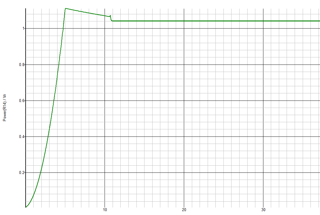
I am using UC3844 and I am getting pretty high Startup resistor dissipation in Steady state? I was thinking Startup resistor plays role only at startup and in steady state the power is drawn from Auxiliary. But looks for peak current required for Mosfet Turn on is supplied by this start up resistor and causing a power loess in steady state. I am having 200-500V input and 10W multiple output DCM and I am using 220K startup resistor. I am attaching the power dissipation. Any idea why we get continuous power dissipation across startup resistor.


  • TI has written an article on reducing this power dissipation and it is published here
    http://www.low-powerdesign.com/article_TI_King.htm

    Your issues is that the 220k is always connected between the 500V  input and the VDD pin of the ic.
    Once the power supply is up and running, you can use a transistor arrangement to switch the 220k out of the circuit.

  • Hi John,

    Thanks for your quick reply. What I am observing is the Chip is taking mean current 23 mA, 20.7mA from Aux and 2.3 mA from startup resistor in steadys state.

    Is that normal? I having trouble to understand the datasheet parameters. It says normal operating current is 17 mA and startup current is 1mA. I observing startup current more than the datasheet.

    Another problem is if I have resistor more than 220K it is not starting for lower voltages such as 200V?

    What should be the range of start up resistor value?

    Regards,

    Chaitanya

    Chaitanya

  • Hi Chaitanya,
    According to the data sheet, the operating current for the UC3844 is 11mA to 17mA at VCC = 15V.
    It is likely that your VCC is higher than 15V and that would explain the slightly higher current.
    The ic needs 0.5mA to 1mA to startup and the startup voltage is 16V so the value of the resistor is (Vmin-16)/1mA. That is how you select the resistor value.
    At higher input voltages the current is of course higher through this resistor but that is the price you pay for requiring a lower startup voltage.
    Regards,John
  • Hi John,

    thank you for the answer. Just last question by VCC you mean the Auxillary supply is that correct? Yes I have bit more as 20V, I don't have external zener but looks like if I used lower VCC then I can use higher startup resistor. There are some chips in the same configuration with lower UVLO is that what your pointing out to? If I take a chip with slighly lower UVLO and used a zener then probably I can reduce the steady state power dissipiation.

    Howeve my question still remains why is the chip drawing power from startup resistor in steady state ( Non -startup state) ? why not from Auxillary supply with low resistance path?

    Regards,

    Chaitanya
  • Hi Chaitanya,
    The reason the circuit continues to draw power from the startup resistor is simply because it is still in the circuit. You need to switch the resistor out of the circuit once the system starts up. This means you need additional .
    John