This thread has been locked.

If you have a related question, please click the "Ask a related question" button in the top right corner. The newly created question will be automatically linked to this question.

bq24232 Charge Complete

Other Parts Discussed in Thread: BQ24232

I've designed in bq24232 part.  It is a great part but I've notice after charging is complete there is a current drain from the battery while external power is still attached.  There are periodic current pulses into the battery.

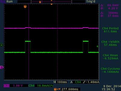
There seems to be a  60mS wide battery maintenance current (17mA) pulse that occurs every 660ms.  However, in between these charge pulses the battery is discharging by 8-9mA . Using a digital o-scope and integrating from one charge pulse to another shows an average discharge rate of 4.1mA.

From battery datasheet we are using it starts the battery is a polymer  Li-Ion, 110mAHr with a nominal 3.7v voltage and 4.2v charge voltage.  Given the capacity and average discharge of 4.1mA we'll need to recharge the battery in 10-11 days.

Once charged, the battery will slowly discharge until the some threshold where bq4232 part will initiate a charge cycle.  Is this the way the bq24232 should operate?

This seems to wear out the battery unnecessarily.  

Thanks for your support.

  • Hi Mike,

    The part will restart charging once the battery voltage drops to 100mV below the regulation voltage. However, we don't expect the charging and discharging pulses happen after the charging is completed. Can you share your schematic with us so we can take further look?

    Thanks,
    Wenjia
  • Wenjia,

    I've done quite a bit of testing with different production boards and different batteries of the same type.

    The part is marked as "NXK, TI 35i  A4GC" Here is how the circuit is wired.

    TS  (Pin 1) connected through 10K to ground.

    BAT (Pin 2, 3) shorted together and connected to 3.7v Li-Battery 1100mAHr

    CE  (Pin 4) shorted to ground.

    EN2 (Pin 5) shorted to OUT (pins 10 - 11)

    EN1 (Pin 6) shorted to ground,

    PGD (Pin 7) weakly pulled high through 100k

    GND (Pin 8 and power pad under chip) connected to GND.  (PwrPad geometry as suggested in datasheet).

    CHG (Pin 9)  weakly pulled high through 100k

    OUT (Pins 10 - 11).  OUT is loaded with < 10mA.  (Results don't change when loaded up to 350mA)

    ILIM (Pin 12) - unconnected

    IN  (Pin 13) connected to a USB hub with voltage measuring 5.15v at bq24232 pin.

    TMR (Pin 14) unconnected

    ITERM, (Pin 15) unconnected

    ISET (Pin 16) connected to ground through 3.32K resistor.

    BAT, and IN has high quality 0.1uF ceramic caps very close to the part.

    OUT has high quality 0.1uF and 10uF ceramic caps also close to the part.

    My understanding of part configuration

    EN1=L, EN2=H  sets ILIM, max input current to 475mA nom.


    ISET set fast battery charging current to 870 AOhm / 3.32K = 262.0mA nominal

    Since ITERM is unconnected, termination current is 10% of 262.0mA = 26.2mA

    The following is a  d-scope capture with the part showing charge complete (CHG goes high).

    The trace in green is from a Tek clamp-on low current probe, where a positive current value is current flowing into the battery..  The microcontroller on board is permanently held in reset during all of the the testing.  I load the output with power resistors to simulate loads ranging from 10mA to 350mA however the load current doesn't affect the o-scope plots.

    As you can see, from the plot the current is flowing from the battery even when power is connected to the circuit and the bq part is not loaded.  The average current is from pulse to pulse is (-4.144mAsec / 0.6116sec) = 6.7mA which will slowly discharge the battery unitl Voreg - 100mV.  This average current seems excessive.  Do you have any thoughts or is this how the part works ?

    Could this be a counterfeit part ?

  • Hi Mike,
    EN2 = H and EN1=L will set the input current limit to whatever programmed by ILIM resistor, however, it seems you don't have one connected to the ILIM pin. Can you quickly verify if this caused the issue? You can either pull EN2 low and EN1 high to set ILIM to 500mA or keep the EN1/EN2 settings as is but connect a 3k resistor to ILIM pin.

    Thanks,
    Wenjia
  • Wenjia,

    You are correct.  I tried two different configurations with same effect as show on the o-scope. 

    In the first config we tested has EN1=0 and EN2=1 with a 3.32K resistor to ground on ILIM pin 12.

    The second config we had EN1=1 and EN2=0 with the resistor on ILIM pin 12 removed.

    We think we have resolved our problem.  There seems to be an interaction with LI battery resistance and battery detection with the part.  Using a different battery current measurement cabling seems to have resolved the current pulsing.  DMM on current measurement introduces an in series resistance.  The amount of resistance is dependent on current scale.

    We'll test more parts and let you know.  Thanks for your support.

    Mike L.