This thread has been locked.

If you have a related question, please click the "Ask a related question" button in the top right corner. The newly created question will be automatically linked to this question.

TPS61175 output current problem

Other Parts Discussed in Thread: TPS61175

Hi all,

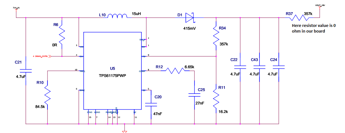
I am using TPS61175 boost converter for up converting 7.4 V to 28 V/450 mA. But when i connected this 28 V to other device, this voltage is getting dropped drastically even with less than 100 mA . Please help me how to solve this problem.

I am the same circuit which webinch tool provided. Please let me know what are all components will affect for voltage dropping.

Thanks

Rave

  • please check the waveform Vin, Vout, inductor current to confirm the input voltage not out  of spec. and inductor current not saturation.make sure Vin and Vout are measured near the device.

    could you share you schemaic if possible? the layout is also very important. i would suggest follow the datasheet and the EVM.

    Jasper

  • HI Jasper,

    Thanks for your reply. I selected the inductor which you suggested in webinch.

    Here i attached the schematic and layout.

    I followed same values in webinch and layout also same as EVM.

    Reagrds,

    Ravi

  • i don't see problem in the schematic. would you attach your PCB? and could you check the waveform when the VOUT drop happen as i told. based on your description, the device operates well in light load, but VOUT drop in 100mA. correct?

    thanks
    Jasper Li
  • Hi Jasper,

    Thanks for your reply and i forgot to attach my PCB file, i will attach it my next post.

    As i told the output voltage is getting dropped after 100 mA (this voltage i connected to Electronic load, not actual load), when i connected this voltage to actual device (RFHA1003_It is GaN Power Amplifier device, It required drain voltage as +28V it is getting dropped even less than for 40 mA. Could you please let me know the problem?

    Thanks & Regards,

    Raveendra.

  • i don't know why this happen. that is why i want you to help to check the waveform of input pin, output pin and inductor current waveform. maybe we can find the root cause from the operating waveform.

    and i suggest you can apply TPS61175EVM for reference.

    thanks

    Jasper Li

  • Hi Jasper Li,

    Thanks for your reply. I will check the wave forms of Input and output pin. May i know what we can see in these wave forms and how we will come to know becasue of what this problem is occuring?

    I don't have TPS61175EVM to take reference.

    Thanks & Regards,
    Raveendra.
  • have you attachment the PCB? I don't see it.

    when debugging the power circuit, i would check the schematic and PCB firstly; then i'll check the device and its external component is soldered well; then I'll measure the voltage and waveform of every pin of the IC, make sure their voltage is the value as expect.
    as you mentioned the device can operates at no load or very light load, i guess the logic pin and signal pin of the IC is good. so i want to check the power pins voltage. i also want to check the SW pin to check if the device is switching normally.

    you can apply an EVM from TI.com

    thanks
    Jasper Li
  • Hi Jasper,

    Thanks for reply. I didn't attach the PCB since i don't have right now, I will send later, Meanwhile i have some doubts. In my circuit i shorted both grounds like AGND and PGND, Does it create any problem?

    Is it required to provide sufficient copper area around the TPS61175 device for proper disipation to get enough load?

    As you said i measured the voltages At Vin i got 7.4 V, At SW pin 3.00 V and At FB Pin i got 1.234 Volatge. One more thing when i hold DMM probe at SW pin, my input voltage is going down and current going to CC, When i removed everyting is fine. When i measured i took proper care like didn't short with any ground.

    Regards,
    Ravi
  • The AGND and PGND must be short, but they should be short in single to avoid noise coupling.

    do you have a oscilloscope to measure the waveform? I want to know why SW is only 3V when VIN is 7.4V.

    thanks
    Jasper Li