This thread has been locked.

If you have a related question, please click the "Ask a related question" button in the top right corner. The newly created question will be automatically linked to this question.

TWL6030 NRESPWRON

Other Parts Discussed in Thread: TWL6030

Hi,

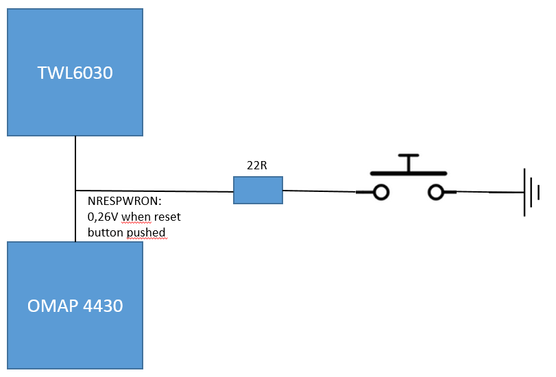
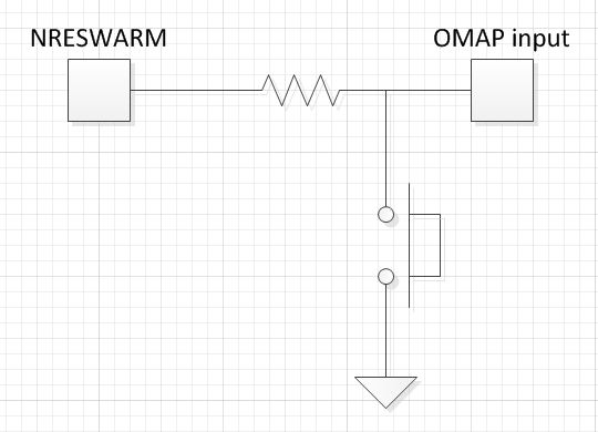
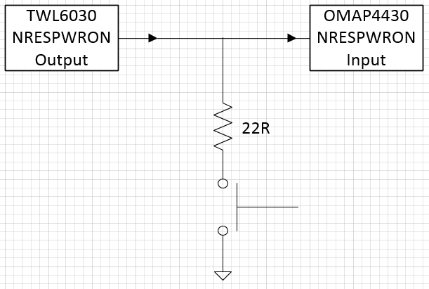
I would like to add a manual reset button in parallel to the NRESPWRON output pin (N5) of the TWL6030. This output pin is internally pulled up in the TWL6030.

Is the NRESPWRON pin an open-drain ouput? Is it allowed to have a manual reset button in parallel to this TWL6030 output pin?

Best regards,

Jens

  • Hi, this output is a push-pull so this is not recommended.

    Best regards, Alain.

  • Dear Alain,

    Thank you for your reply!
    Would adding a reset button to the NRESPWRON signal be allowed if a small series resistor is added?
    We would like to use this as a workaround because we experienced an issue where the NRESWARM functionality of the OMAP we use isn't working properly. Using the NRESPWRON instead would provide us a workaround.

    Best regards,
    Jens
  • Hi Jens, yes this should work fine. Best regards, Alain.
  • Hi Alain,

    We will add a 22R series resistor. By this, the voltage on the NRESPWRON will drop to 0,25V. 
    Do you think this should be OK to protect the output of the TWL6030? We measure a peak current consumption of about 10mA when the reset button is pushed.

    Best regards,
    Jens

  • Hi jens, on which side of the resistor do you see 0.25V: TWL6030 or OMAP? I guess it is on PMIC side which is not very good I think. By the way this may cause some logic side effect as well as this signal is used internally by the logic during reset stage. Why not using a bigger resistor value in this case?

    Best regards, Alain.

  • Hi Alain,

    Our setup is as in the schematic below. If the resistor value becomes higher, then the voltage level at the OMAP when the reset button is pressed will go higher as well. When this voltage level becomes too high, the OMAP will not see the reset.

    Is there a risk in damaging the TWL6030 output when implementing this way?

  • Hi Jens, I thought you have implemented something like this:


    This would prevent short-circuiting TWL6030 output and avoid a possible partial reset inside PMIC logic.

    Best regards, Alain.


  • Hello Alain,

    Thank you for your reply!

    Can you indicate what resister value you would suggest in the circuit you included in your previous post?

    Please note that my question is about the cold reset ouput pin of the TWL6030: NRESPWRON, not the warm reset input pin of the TWL6030.

    Our implemention is shown in the image below. Despite from the pin name indicated in your drawing, the setup seems quite similar. Differences are:

    1. NRESPWRON is an input pin of the OMAP, and will not influence the NRESPWRON signal. The different location of the resistor will only have an impact on the voltage level of the signal at the OMAP. As long as the voltage level is within the range specified by the OMAP, the funcctionality should still work.

    2. When the push button is used, the push-pull output of the TWL6030 will be connected to GND via a resistor in your and in my drawing. You indicated in an earlier posting that a small series resistor should be sufficient in order not to damage the NRESPWRON output pin of the TWL6030. What value would you recommend?

    Looking forward to your feedback!

    Best regards,

    Jens

  • Hi Jens, sorry I meant writing NRESPWRON instead of NRESWARM in my schematic. 1Kohms resistor or above should be fine. Your implementation is not correct as it may cause a partial reset in TWL6030 logic because even though it is an output to the device this signal is re-used internally to control some gates. Depending on its levevl I'm concerned that logic may misbehave. In addition 10mA is significant for a buffer which is designed to deliver up to 2mA only.

    So overall I would not recommend it and I'd suggest my proposal instead (using NRESPWRON signal, not NRESWARM).

    Best regards, Alain,

  • Hi Alain,

    Thank you for your reply!

    When we use a 1k or more resistor, the voltage level at the omap input pin does not go low enough to initiate a cold reset...
    So far, we tested with different resistor values (0R to 100R) to limit the current but for some reason is the current always 10mA. Do you know why? Is the pin designed as a current source?
    We currently have the reset button connected to the warm reset input of the omap and the twl6030. However, the omap stops in its boot cycle before x-loader when a warm reset is triggered. The twl6030 has the warm reset as an input, can we let the twl6030 initiate a cold reset when it detects a low on NRESWARM?

    Looking forward to your feedback!

    Best regards,
    Jens
  • Hi Jens, the 1K resistor should be placed in serial like shown in my schematic, not in parallel. In this case OMAP will see the low level set by the switch, not NRESPWRON

    When NRESPWRON pin is loaded by 22 Ohms I think the internal LDO supplying it may enter in drop zone so current is limited. Anyway 22 Ohms is way too much load for this output buffer.

    NRESWARM cannot be programmed to initiate a cold reset unfortunately.

    Best regards, Alain.


  • Hi Alain,

    In mean time, we tested the 22 ohms load setup as I drawed in a previous posting for 9 days:
    - One setup has the reset button pushed in continiously. This means that the NRESPWRON pin is loaded by 22 ohms for more than 200 hours. We measure a current consumption of 10mA.
    - A second setup has the reset button toggled every 1,6 seconds. This to load the pin with the peak current when the signal is pulled low. In total more than 480.000 reset pulses were given to the NRESPWRON pin.
    Both devices are still working correctly after these 9 days.

    Can we rely on the test results (and the internal protection of the NRESPWRON pin) to implement this workaround? Or would you advice not to use this workaround?
    Normally, this signal will only be used a very short time (a few minutes) during the lifetime of the product.

    Best regards,
    Jens
  • Hi Jens, according to your experiments it looks ok then but I cannot guarantee it as this is not part of the normal usage of the PMIC.

    Best regards, Alain.