This thread has been locked.

If you have a related question, please click the "Ask a related question" button in the top right corner. The newly created question will be automatically linked to this question.

Problems in referencing the design UCC28700EVM-068

Other Parts Discussed in Thread: UCC28700EVM-068, UCC28700

Hi,

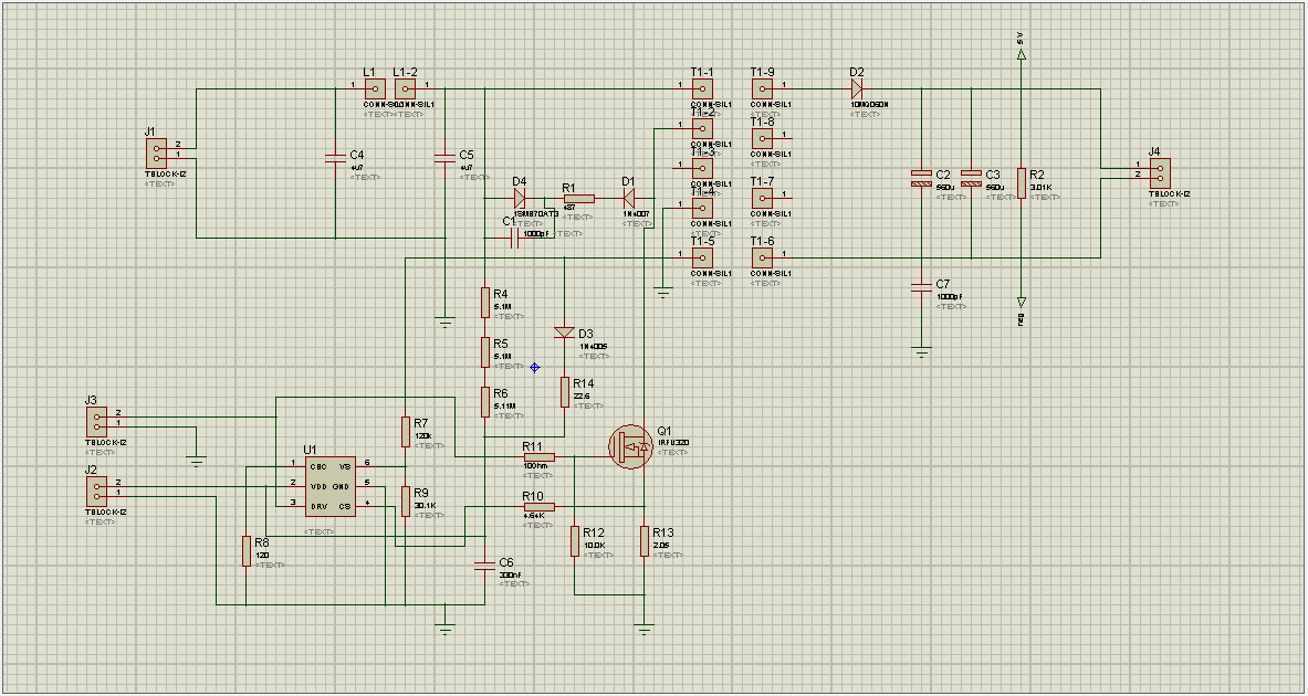
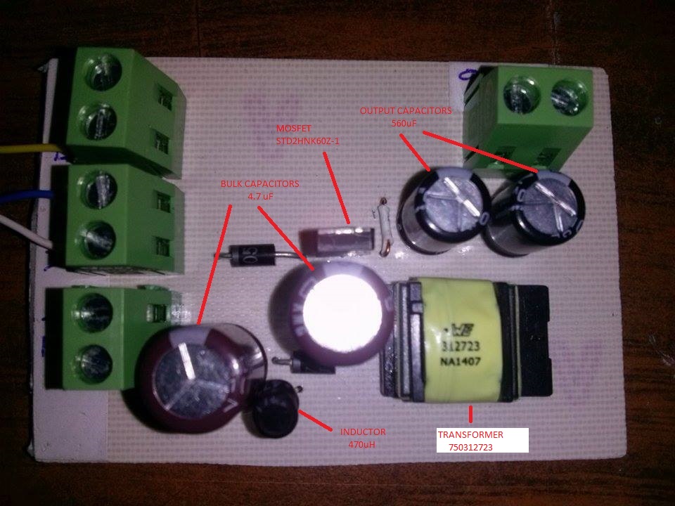
I'm working in referencing the design UCC28700EVM-068 and I have had some issues with. I took as reference for my design the attached files on TI home page, http://www.ti.com/tool/UCC28700EVM-068?keyMatch=UCC28700EVM-068&tisearch=Search-EN#Technical Documents. I made a board following user's guide for UCC28700EVM-068 and followed the specifications in the file (design & materials) and my AC/DC converter doesn't work. I tried to test UCC28700 separately to watch PWM output signal to drive the mosfet, according with the UCC28700 technical document, and I didn't get anything. What can it be my problem? or any suggestion to make working my board or modify it. 

  • The UCC28700 will function as per the datasheet only if the input signals are within the range specified. If this is not the case then the protection features (overvoltage,low line,over current) will shutdown gate drive pulses.
    Do you have a schematic of the test circuit?
  • John Griffin1 said:
    The UCC28700 will function as per the datasheet only if the input signals are within the range specified. If this is not the case then the protection features (overvoltage,low line,over current) will shutdown gate drive pulses.
    Do you have a schematic of the test circuit?

     Thanks for reply. This is an image of the test circuit. It is very similar to original circuit that I used with the difference that test circuit doesn't have ac current rectifier. I'm using an external dc power supply to supply the circuit and I included some test points.  The points T1-1, T1-2.. etc mean transformer connections pins, and points L1 and L1-2 mean inductor connections pins.

  • Is there a transformer on this board?
  • Yes, the points T1-1, T1-2..., etc represent transformer connection points. The schematic was made in a CAD software, it is the reason because the transformer doesn't appear in the above image, only connection points. The specific transformer footprint doesn't exist in the software that I'm using. 

  • It looks like you used 120 Ohms on the cable compensation pin. This will cause the converter to shutdown.
    10k is about the min value here
  • Hi John,

    In the image appears a 120 Ohms resistor connected with CBC pin of UCC28700, actually in the PCB I'm using a 10 KOhms resistor. I used a standard footprint because CBC resistor doesn't have fixed value. Also I tried two configurations for CBC, with resistor (10 Kohms as minimal) and without resistor (as UCC28700EVM-068 design ) and both configurations haven't worked
  • You need to capture at least some scope waveforms.
    Start with VDD , GD and IS. The datasheet describes the startup beswitching behavior. If you don't see any switching then either the circuit is not built as you think it is or the ic is damaged.