This thread has been locked.

If you have a related question, please click the "Ask a related question" button in the top right corner. The newly created question will be automatically linked to this question.

external clock synchronization of LM5021 PWM

Other Parts Discussed in Thread: LM5021, LM5088

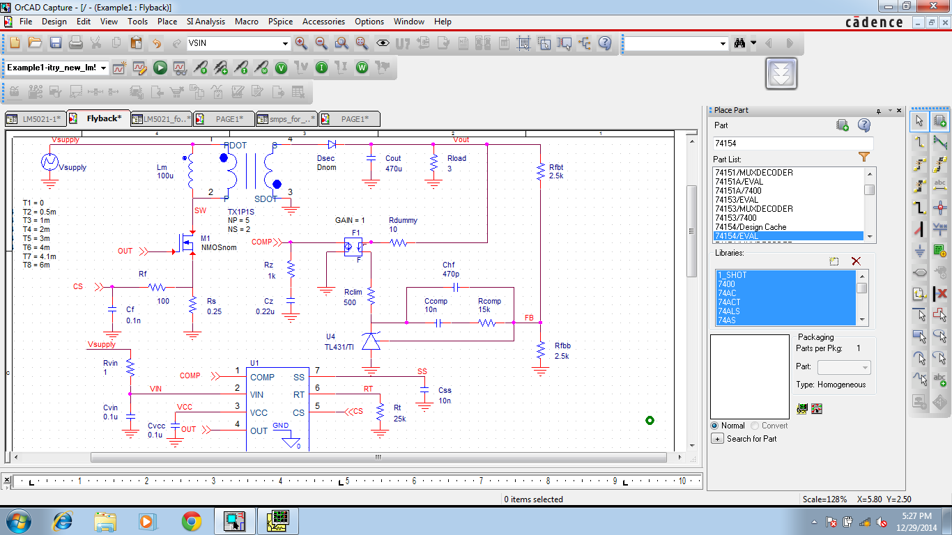
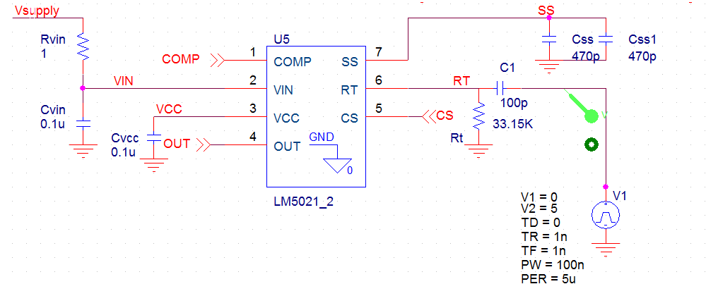
This is an original flyback converter from TI website. If the PWM controller LM5021 is to be driven by an external clock input at pin RT, how would the input circuit at pin RT look like? RT pin is used for external clock synchronization. How should be the external clock signal?? Square wave?? with what duty cycle??

  • Akhilesh,

    The clock signal should be capacitively coupled into the RT pin with a 100pF capacitor. A peak voltage level greater than 3.8 V at the RT pin is required for

    detection of the sync pulse.  The sync pulse width should be set between 15 ns to 150 ns by the external components. The RT

    resistor is always required, whether the oscillator is free-running or externally synchronized.

    Terry Allinder

  • I have connected a 33.15K resistor at RT pin which sets the free running oscillator frequency to 100KHz. A 200KHz (which is greater than 100KHz free running frequency, as demanded by the datasheet) pulse train is coupled to RT pin via a 100pF capacitor. Even though the PWM controller is externally driven by a 200KHz clock, the output of the controller is still at 100KHz, why??? Is the external clock signal ( 5V, pulse width of 100ns, 200KHz) wrongly fed?? if yes, the pls suggest corrections.

  • Akhilesh,

    I would normally set the oscillator frequency closer to the desired sync frequency, in this case 160 kHz - 180 kHz.  Can you use an oscilloscope and capture the following signals: the sync in signal, the sync in signal measured across the RT resistor, and the OUT signal

    Terry

  • If equal or similar sync technology is used in LM5021 as in some other devices such as LM5088 then you should take into account the following notice: "The free-running frequency should be set nominally 15% below the external clock frequency and the pulse width applied to the RT/SYNC pin must be less than 150ns. Synchronization to an external clock more than twice the free-running frequency can produce abnormal behavior of the pulse-width modulator."
  • Sir, as per your comment now I tried to keep the free running oscillator frequency to 100KHz and set the external clock to 115KHz.... the graphs of these signals are as follows

    1) external clock(115KHz)

    2)Across RT resister (clamped to 2V with a zener diode as per datasheet)

    3) output signal

    Even after doing this, m getting output 100KHz....that means its not synchronizing to the external clock.

  • Maybe you should try it with different duty ratio of external signal (like 20-80 or 40-60). Current one seems to me pretty low/narrow.
  • datasheet of LM5021 says the pulse width of external sync clock should be between 15n to 150ns, therefore ON time cannot be changed to more than 150ns...my requirement is to clock it at more than 100KHz...say 125Khz though external clock which amounts to 8us cycle time...therefore duty cycle is 150ns/8us which is too small..there's no was I can get a duty cycle of 40-60 or 20-80(strictly speaking as per datasheet)
    But, I tried increasing pulse width keeping cycle time 8us (100KHz)...so tat duty cycle is 40%....still the output remains at 100KHz(which is set by RT resistor value). PWM chip doesn't respond to my external clock.

  • There is something wrong with your SYN signal (the voltage across the RT resister). There should be a positive going spike greater then 3.8V  for the controller to detect a sync signal.  The maximum pulse with at the RT pin is 150ns.

    From the data sheet"The external clock must have a higher frequency than the free running oscillator frequency set by the RT resistor. The clock signal should be capacitively coupled into the RT pin with a 100pF capacitor. A peak voltage level greater than 3.8 V at the RT pin is required for detection of the sync pulse. The dc voltage across the RT resistor is internally regulated at 2 V. Therefore, the ac pulse superimposed on the RT resistor must have 1.8-V or greater amplitude to successfully synchronize the oscillator. The sync pulse width should be set between 15 ns to 150 ns by the external components."  

    Terry