This thread has been locked.

If you have a related question, please click the "Ask a related question" button in the top right corner. The newly created question will be automatically linked to this question.

bq27510-G3 relaxation mode

Other Parts Discussed in Thread: BQ27510-G3

I'm looking to use the bQ27510-g3 in a design in which the target circuit spends a lot of time in a low power state. When this occurs, I need the gas gauge to still accurately report the battery.

My understanding of the bq27510-g3 is that below a certain current (quit current) the part enters a "relaxation" mode and primarily uses the battery voltage rather than coulomb counting. However, in my tests to date this doesn't seem to happen and the battery capacity keeps ticking down at a higher rate.

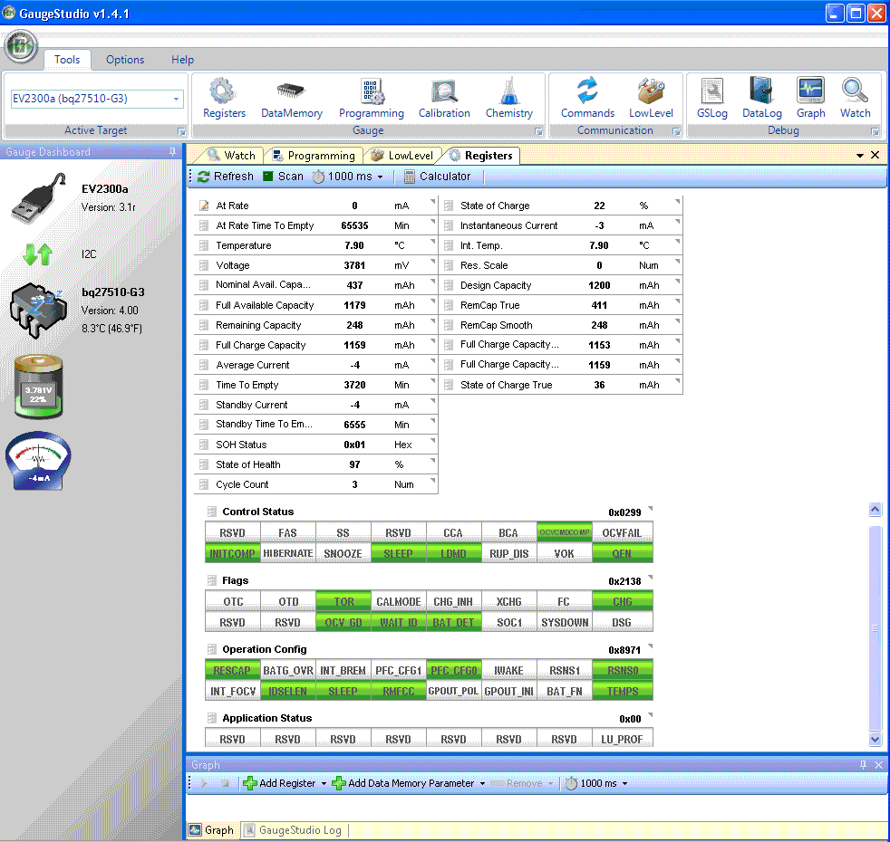
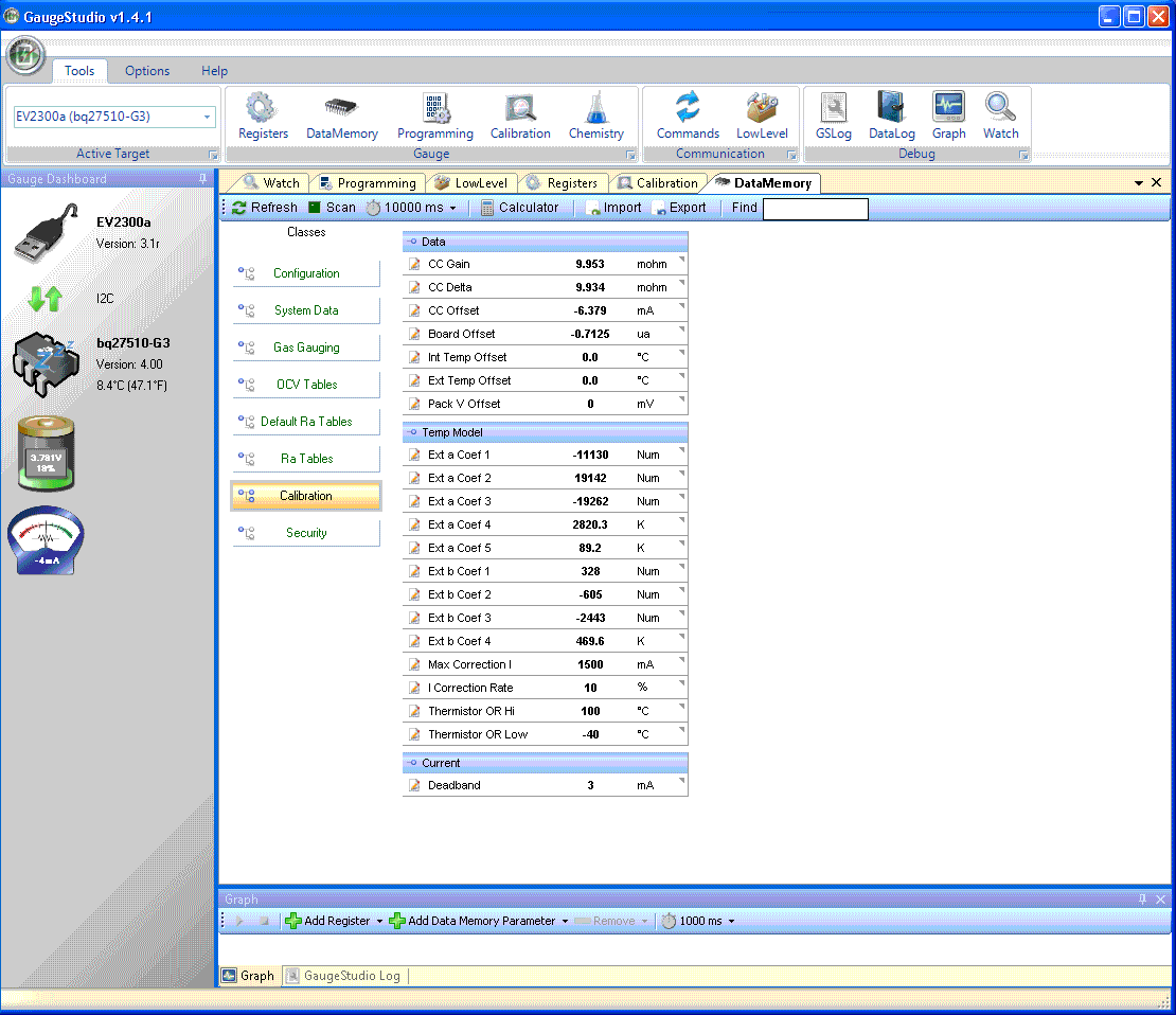
I have a test board that is hooked up to Gauge Studio and the current drawn by the circuit is around 100uA (the lowest current the gauge seemed to be able to report is 3mA). Below are some screenshots of the gauge readings 24 hours apart and also the configuration / parameter pages. Note the Capacity has gone from 22% to 18% whereas the battery Voltage has only dropped 1mV. If I disconnect the battery and reconnect, I go back to 22%.

I'm sure there's something simple I haven't done here, can someone point me in the right direction?

  • Hello Jon,

    I have a couple of questions:

    1. In the screen captures I see that the gauge is reporting -4 mA.  Is this the type of load that is seen on the battery?  Or is this "ghost" current seen by the gauge?
    2. Have you completed board offset calibration?  If no current is flowing the gauge should not report current.

    One of the trade-offs to SOC smoothing is that the filtered SOC is only allowed to jump/drop on the following conditions:

    1. End of discharge (i.e. terminate voltage has been reached)
    2. End of charge (i.e. the gauge has detected charge termination)
    3. In relaxation where the temperature as changed more than the specified DoDatEOC Delta T dataflash (DF) parameter value.  This value defaults to 5 C.  What this means is that if the temperature changes by more than 5 C the gauge can re-compute the Remaining Capacity due to the change in temperature.  The filtered SOC is allowed to change if this happens as long as the [RCJUMPOK] bit in the OpConfig D register is set (it is cleared by default)

    The behavior you are seeing appears to be because the gauge is detecting small amounts of "false" charge accumulation which makes the filtered SOC go down.  The true SOC can also go down, but the true SOC can correct itself based on a voltage measurement and jump back up/down to the correct SOC value (assuming the accumulated charge is "false").  Looking at the screen shots you can see the "State of Charge True" register is staying at 36% (it should read % and not mAh, we will look to update that).

    We would recommend looking into the board calibration or possibly disabling SOC smoothing.

    I hope this helps.

  • Jared,

    Thanks for the reply. The current is definitely a "ghost" current as the actual system draw at this point is only around 100uA. If you disconnect the battery and reconnect it, you go back to the original SOC.

    I haven't done a board offset calibration, so this could be the answer. I'll have to look into how to do that (+your other suggestions) and report back the results.

    Jon

  • Hi Jared (or anyone with an answer),

    I've done some more tests and performed both a CC calibration and Board offset and this has improved things. However, the SOC still goes down at a rate higher than I would expect and you can "correct" it back by plugging and unplugging the battery.

    I have a few more questions:

    According to the Impedance Track algorithm White Paper:  "The algorithm uses current integration(coulomb counting) when the system is ON, and open-circuit voltage measurement when the system is OFF or in SLEEP to adjust remaining state-of-charge (RSOC)". I thought that once the current was below the "Quit Current" it uses the OCV. If this was correct, then I wouldn't expect to see the errors that I'm seeing as the current in this test is permanently below the Quit Current. Is this not correct?

    Is there a way of achieving the same effect as plugging and unplugging the battery in software? Thus resetting the measurement.

    I've enclosed a screenshot of the system post calibration. You can see that the Average and instantaneous current are now 0. However the Standby current is -1mA. What is this and should it be 0mA too?

    Jon