This thread has been locked.

If you have a related question, please click the "Ask a related question" button in the top right corner. The newly created question will be automatically linked to this question.

“Application Circuit When VTT Is Not Required” for TPS51216

Other Parts Discussed in Thread: TPS51216

Hello Team,

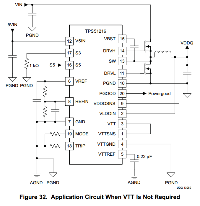
I’d like to ask you about “Application Circuit When VTT Is Not Required” (datasheet page.19) for TPS51216.

http://www.ti.com/lit/ds/symlink/tps51216.pdf

-----

Q1

>Select MODE 0 or MODE 1 shown in Table 2 (Select Non-tracking discharge mode).

What is concerned about if we use MODE 2 or MODE 3?

Q2

>Maintain a 0.22-µF capacitor connected at VTTREF.

What is concerned about if there isn’t capacitor?

Q3

>Pull-down S3 to GND with 1-kΩ resistance.

Could you tell me the reason why does this pull-down resistor need?

What is concerned about if we short S3 to GND?

-----

My customer has above questions because there was no information for his datasheet(Original:November 2010) when he started to use this device.

Regards,

Hidetoshi Matsunami


  • Q1. You want to use Mode 0 or 1 to select "non tracking" since you do not use both VDDQ and VTT.
    Q2. VTTREF is derived from VDDQSNS. It is still active when not using VTT and must be terminated with the 0.22uF cap.
    Q3. S3 current must be limited to 1 uA. Use the 1k pull down as suggested.
  • Hello John,

    I'd like to ask you some additional questions.

    Q1. >You want to use Mode 0 or 1 to select "non tracking" since you do not use both VDDQ and VTT.

    • Could you tell me what is occurred if MODE pin resistor is 200kΩ(MODE3) or 100kΩ(MODE2) at the schematic of Figure32?

     I believe it is no problem for discharge operation because the mode changes to non-tracking discharge by itself.

    >(datasheet page 16)After 4 ms of tracking discharge operation, the mode changes to non-tracking discharge.

    If there is any concern, please let me know.


    Q2. >VTTREF is derived from VDDQSNS. It is still active when not using VTT and must be terminated with the 0.22uF cap.

    • Thank you for your answer. I understood.


    Q3. >S3 current must be limited to 1 uA. Use the 1k pull down as suggested.

    • Datasheet shows S3 is input pin, so I believe S3 current doesn't flow if S3 is short to GND only.

    I can't understand why 1kohm pull down is required as Figure32.

    Could you tell me the detailed reason?

  • I do not have any additional information at this time.  Let me see if I can find out.

  • Hello John,

    I appreciate your support.

    I would appreciate it if you could find out as soon as possible because this device is already used in my customer's design and he has to make a quick judgment whether he needs to change his design or not.

    Best Regards,

    Hidetoshi Matsunami

  • It may take a while to find out. If you are in a hurry I would suggest that you follow the datasheet recommendations exactly and not worry about "why".