This thread has been locked.

If you have a related question, please click the "Ask a related question" button in the top right corner. The newly created question will be automatically linked to this question.

Trickle Charging BQ51050B and BQ500212A

Other Parts Discussed in Thread: BQ500212A, BQ51050B, BQ25100, BQ51003, TIDA-00318

Dear All,

I am troubleshooting a wireless charger/receiver solution using BQ51050B and BQ500212A. The following sequence is currently taking place:

* Charge up to 4.2V works as expected (blinking green LED)
* "Charge Complete" appears to work as expected since I get a solid green LED for 5 seconds, followed by the green LED being off. I also see a drop of the battery voltage when this happens.
* About 1-2 minutes after this, the charging process starts again. And terminates with a "Charge Complete". This appears to go on forever.

Topping up the battery (i.e. tricke charging) every few minutes seems to be a bit too frequently in my opinion. Is this normal?

I read in the BQ500212A datasheet that "If the reported charge status drops below 90% normal, charging indication will be resumed.". I can not, however, find out what 90% of reported charge status means. Is it related to voltage? Current? Something else?

I use a maximum charge current of 75mA, and have the termination set to ~30mA. This is hopefully a temporary solution, but is currently required since the rest of the wireless device consumes between 1 and 20mA depending on the current workload. I assume that this means that I can not use a charging termination current of less than ~30mA since the charging would not report charging complete reliably. However, I am a bit worried that this means that the battery will not fully charge.

In summary, I have the following two questions:

* Is a trickle charge frequency of ~1-0.5/min normal?
* If not, how is the "90% charge status" calculated?
* Could this be related to my high termination current?

  • Martin,

    The bq51050B has a recharge threshold (VRECH) that will re-enable charging.  Nominal value is 110mV below charge voltage (nominally, 4.2V - 0.11V = 4.09V). When the bq500212A receives the charge complete signal from the bq51050B it terminates power transfer.

    The bq500212A will continue to cycle between sleep and "ping" mode.  During the ping, the bq51050B will power up, measure the voltage on the BAT pin and send a response to the bq500212A.  If the voltage is still above the recharge threshold, it will send another charge complete signal.  If the voltage on the BAT pin drops below the recharge threshold, the bq51050B will re-enter charge mode.  In this case, it will most likely be in the taper mode.

    How much of a drop in the battery voltage are you seeing?  This could trigger the recharge.  Generally, I do not see a large drop in Battery voltage at termination.

    Note that the bq51050B may not be the best choice for low power charging and very low termination currents.

    I recommend the bq51003 wireless receiver and the bq25100 low power charger for these types of applications.  Please see the TI design TIDA-00318.  It can be found on TI.com by searching for TIDA-00318 or searching in the TI Designs portion.  The direct link is:  www.ti.com/tool/tida-00318.

    Regards,

    Dick

  • Thank you for a fast reply.

    4.09V is in line with what I see in my measurements as well.

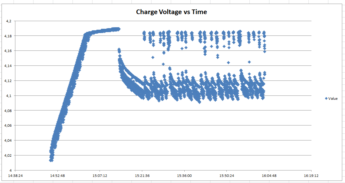
    I have provided a plot that shows the voltage over time. I see a rather significant drop-off in battery voltage. The voltage is measured over the battery using a digital multimeter with computer logging functionality.

    It just occurred to me that the battery on this device has been in the lab for quite some time, I will try with a new battery the next time I have an opportunity (early next week).

    I understand that the BQ51050B is not the best choice for this purpose (also based on replies to other threads on e2e), but I have recently inherited this project and am currently not able to change the charging solution due to a tight schedule to a prototype delivery. I will however consider the BQ51003 and BQ25100 solution for the next batch of prototypes which are most likely scheduled for later this year.

  • Martin,

    Great plot for analysis.  We do the same thing for our testing.

    A simple proof of concept is to change the termination current to 20mA.  If that adds more capacity to the battery, it'll be shown as longer time between recharge cycles.  

    What load is on the battery?  After the initial drop, it still decays quickly.

    Swapping batteries as you plan to do is also a good idea.

    Regards,

    Dick

  • Dick,

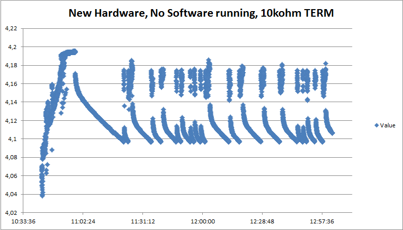
    I just got back to our lab and replaced the old battery with a new one. The result was unfortunately not what I expected at all. I attached a plot below:

    Two important differences are obvious:

    1/ The voltage level is noisier
    2/ The trickle charging terminates before even reaching 4.2V

    I have looked at the LEDs at the charging station, and it appears as if the charging station receives a "charging complete" indication since the green LED is on for ~5 seconds before turning off.

    What could cause the charging to terminate before reaching 4.2V? I can not find any sensible explanation in the datasheet.

    The current draw should be around 5-20mA (fluctuating depending on the current mode), and the battery has a capacity of 100mAh.

    Regards,

    Martin

  • Martin,

    Is it possible for you to include the bq51050B schematic?  

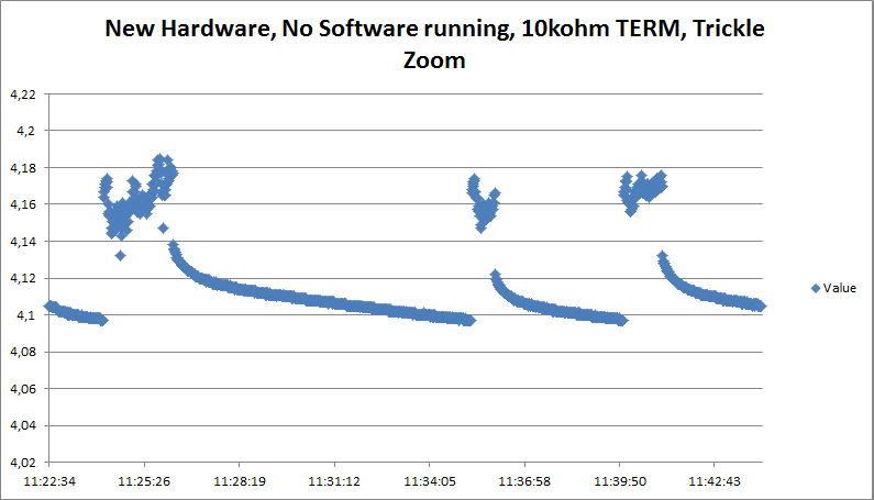
    Can you run the same plot you show above, but zoom into the taper mode so we can get more details of the voltage profile?

    If it's possible to measure the current into/out of the battery, that would be great.  You note the current draw is 5-20mA.  To confirm, that's system draw?  

    Regards,

    Dick

  • Dick,

    The schematic is attached below. The TERM resistor has been replaced with a 10kohm resistor (in wires ~20cm long for easy experimentation, I assume that the TERM terminal is not very sensitive?).

    Plot zoomed in on the taper mode. The two different "DC-levels" correspond to ~2mA system current draw and ~20mA system current draw.

    Yes, the 5-20mA is the current consumption of the wireless device. I am trying to find a suitable measurement device capable of measuring 1-100mA DC, but the multimeters I have access to result in a voltage drop that I believe would interfere with the charging. Do you have any recommendation?

    As a side note, I tried changing the termination resistor (which resulted in never-ending charging). When I changed it back, I get a better curve shown below.

    This plot uses the same hardware as the previous plot. I do not understand why they look so different.

    Also,

    I am looking at page 17 of the B151050B datasheet. The decision to stop charging are:
    * VILIM < VTERM, and
    * Vo>Vrchg

    These acronyms are however not fully defined in the dataheet. Are there interpretations correct?
    * The voltage on the ILIM-pin shall be less than the voltage on the TERM-pin, and
    * The voltage on the BATT pin shall be greater than...? 4.09V..? (VRECH)

    Is there any difference between re-charging a device (that is left on the charging pad) and charging a "new" device (i.e. taking the device off the charging pad and placing it there again)? Edit: The BQ500212A datasheet has a section called "Trickle Charge and CS100" but does not provide any information on the functional difference between the modes, and I can not find any relevant information in the "wpc specification part 1" either.

    Thank you again for your responses, I am a bit confused at the moment.

    Regards,

    Martin

  • Martin,

    Thank you.  This helps.  

    First, your questions on page 17 of the datasheet.  I am revising the datasheet now, so this is good input.  I will attempt to clear up the confusion in the datasheet.

    Essentially your understanding is correct.  The TERM pin has a 50uA current source so it creates a constant voltage based on RTERM.  The ILIM pin has a current mirror (of the battery current).  As a result, the voltage on the ILIM pin will decrease as the charge current decreases.  The comparator on the TERM pin looks at these two voltages (VTERM and VILIM).  When the current on the ILIM pin reduces such that its voltage (IILIM * RILIM) is below VTERM, it is ready to send a termination signal.  The next decision point verifies that Vo (the Battery voltage) is greater than the recharge threshold.  This helps separate pre-charge from taper charge.

    Any other suggestions on improving the datasheet clarity would be appreciated.

    I have another suggested experiment.  It would be interesting to see the battery charge profile without the system load.  Based on the plot above, it is about 5 minutes between recharge cycles.  The biggest drop-off is the initial time after charge termination.  We need to determine how much of that is the load and how much is the battery.  20mA * 5 minutes is (5m * 20mA * 1h/60m) about 1.7mAh. Your system is not running at 20mA the whole time, but there is a drain.  

    I'd suggest charging the battery to termination (without the load if possible) then discharge at a constant load while not on the Transmitter.  Just to see a normal discharge cycle.

    I do not have a better suggestion on the current measurement - unless you have a current probe capable of the low currents.  The experiment above could be used to vary the load currents to emulate the system.

    When I am using the bq51050B in the lab, I use a source meter to emulate the battery.  Doing that, I change the voltage and watch the change on the source meter.  During taper mode, I change the battery voltage slowly to watch the current change.  This helps to determine the true termination voltage and current.  Measuring the voltage at the BAT pin is critical here since any change in voltage at the source meter due to cables and IR drop will impact the measurement.

    Your note above says "The TERM resistor has been replaced with a 10kohm resistor (in wires ~20cm long for easy experimentation".  Is that the TS-CTRL resistor?  The TERM is very sensitive (50uA current source plus low voltage level comparisons), the TS-CTRL will not as sensitive.

    The schematic shows a 2400 ohm resistor on TERM.  That would be a 10% termination current (or 7.6mA based on RILIM).  The accuracy of the comparators at this level could be causing some of the premature termination you've seen.

    "Is there any difference between re-charging a device (that is left on the charging pad) and charging a "new" device (i.e. taking the device off the charging pad and placing it there again)? "  No, there is no difference.  The power transfer start is the same if it is the 1st or 100th time.

    Regards,

    Dick

  • Dick,

    I will try your suggested experiment in some form tomorrow :). I agree that a full discharge cycle would be interesting as well.

    No, I meant the TERM resistor. I will minimize the cable length to reduce the risk of problems with my termination resistor, thank you. The TERM resistor is currently 10kohm, to account for the system load current. Otherwise the charging will never finish. By the way, how long does the current need to be below ILIM for the charging to stop? A couple of seconds?

    Are you sure that there is no difference? When reading the datasheet of the BQ500212A, "trickle charge mode" is mentioned under the heading "trickle charge and CS100". The wireless power specification (part 1) states on page 136 that "For example, the Power Receiver can request to terminate the power transfer—battery fully charged—reverting the system to the selection phase, or request to renegotiate the Power Transfer Contract—change to trickle charging the battery using a lower maximum amount of power—reverting the system to the identification & configuration phase.".

    I find it interesting that, during trickle charging, the battery voltage typically never reaches 4.2V (at least with my setup). I am guessing that the charging is turned off because of a low charging current (ILIM), but why is the voltage not 4.2V in that case? Perhaps it reaches 4.2V and immediately deactivates due to a low charge current, before my multimeter records a measurement.. Seems a bit unlikely though.

    Again, thank you for your response.

    Regards,

    Martin
  • I have an additional plot that shows an interesting trickle charge behavior that could be related to some of my other issues. It is from the new battery, and is a continuation of my previous plot.

    The first "longer change" supplies enough power to keep the unit powered for ~20-30 minutes before reaching the threshold for recharging. A trickle charge is initated, but is somehow not successful (since only a few minutes pass before another trickle charge is initiated, and the charging time appears to be very short). This happes four more times. From that point, the trickle charges supply sufficient power for ~20-30 minutes, the same time that the first "longer charge" provided.

  • Martin,

    It seems to me that the bq51050B is terminating "as expected".  The BAT is lower during the 20mA cycle than the 5mA cycle.  During taper, the BAT transition can impact termination or not.  If the termination threshold is met at 5mA, but not at 20mA, the device may interpret the 5mA duration as terminated, but if the sampling is such that it occurs during the 20mA portion, the BAT droops a bit and may not terminate.

    Regards,

    Dick

  • Dick,

    I still do not understand why the charging can terminate when the battery voltage has not reached ~4.2V. Looking at the curve, it seems to me as if the charging is often interrupted before any significant charging has taken place leadning to a rapid decline in battery voltage thus triggering a new trickle charge round. In some cases, the charging process is allowed to run for a longer time leading to a longer time between trickle charges. How can it be that the battery voltage does not reach 4.2V before charge termination? Doesn't the BQ51050B first to into a constant voltage mode of 4.2V before reducing the current, allowing termination?

    I had a mishap in the lab this morning (not entirely sure how...), rendering the prototype power receiver I was using broken. I have assembled a new device that I will be using for all future measurements. The new device has a SMD 10 kohm TERM resistor. The new device has not yet been programmed with software which means that the current draw is constant. The charging curve for the device looks as follows:

    A zoomed in plot of some of the trickles:

    However, it should be noted that these plots have a termination current of ~30mA, and that software is not executing. I am currently running an experiment where I have a 20mA (200ohm) resistor over the battery, which should result in a more realistic scenario (and also result in a battery with more charge)

    After this, I will do a full discharge cycle with only the battery.


    So, my current questions are:
    - Are you sure that there is no difference between trickle charging and "first time on the pad"-charging? When reading the datasheet of the BQ500212A, "trickle charge mode" is mentioned under the heading "trickle charge and CS100". The wireless power specification (part 1) states on page 136 that "For example, the Power Receiver can request to terminate the power transfer—battery fully charged—reverting the system to the selection phase, or request to renegotiate the Power Transfer Contract—change to trickle charging the battery using a lower maximum amount of power—reverting the system to the identification & configuration phase.". The reason I am asking is that it seems as if the first charge is active for a longer period of time, since the time until first recharge is long.

    - How can it be that the battery voltage does not reach 4.2V before charge termination whn trickle charging? Doesn't the BQ51050B first to into a constant voltage mode of 4.2V before reducing the current, allowing termination?

    - How long does the current need to be below ILIM for the charging to stop? A couple of seconds?

    Thank you

    Regards,

    Martin

  • I can already see that the addition of a 200 ohm (20mA) resistor over the battery made things worse and more confusing instead of the opposite:

    Since the termination current is 30mA, the charging should not terminate until the resulting current into the battery is less than 10mA (since 20mA is dissipated in the bleed resistor). It feels as if the trickles do not supply a sufficient amount of energy. I will leave this experiment running for a while to see if the behaviour changes (although I do not see why it should). The short jump from ~4.10 to ~4.12V at 13:33:36 is because I disconnected and reconnected the 20mA load resistor.