This thread has been locked.

If you have a related question, please click the "Ask a related question" button in the top right corner. The newly created question will be automatically linked to this question.

UCC28710 used for 400V to 12V DC-DC won't start

I am trying to push the limits of this little flyback, ideally I would like to achieve a 100W 12V output.  If this cannot be reached that is fine, but I need to get the controller to turn on so I can evaluate the limits of my circuit.  I have selected a MOSFET that can be turned on by the 25mA DRV pin, and I am using a non-dissipative snubber with the fastest diodes I could find (15ns trr).  I can provide schematic and board layout if that can help.

Here is the hangup:

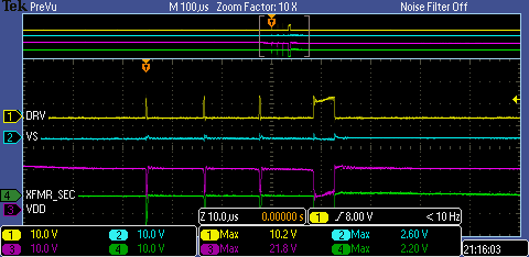
The controller appears to to perform the startup operation described in section 8.4.4 of the datasheet, switching the FET three times with a short impulse. This can be seen in the scope capture below. It then looks as if it is trying to start up as it produces a DRV signal to the gate of significant duty cycle, but then returns to a reset procedure. The circuit behaves this way for a few cycles on startup, and then remains in a low power state where it just produces the initial three pulses with no significant switch following.

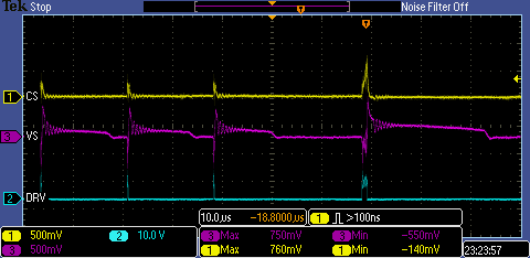
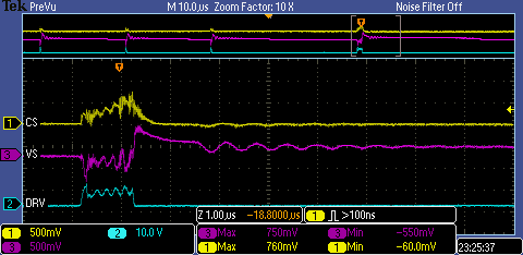
I initially assumed that the controller must be getting a bad measurement as my circuit had some ringing.  I have since improved this and verified that the CS and VS values are well within the limits throughout its operation.  Aside from placing high freq caps on CS and VS, does anyone have advice that can help me get this controller up and running?  What are the possible conditions that would create this behavior?

  • Hi Victor, It would be good to post the SCH file in PDF. Though i think for 100W, you might have a high current MOSFET which might need more current to turn on. the DRV pin supplies typ 25mA, which may not be sufficient for that SW MOSFET.
    regards,
    Narendra
  • Narendra,

    Thanks for the response.  Here is a link to my schematic:

    https://github.com/Victorb101/DC-DC-Converter/blob/master/DC-DC%20Converter%20v1.1.pdf?raw=true

    I do have some new information about the problem, but now I am even more stumped.  I was incorrect in my earlier statement in saying that CS remained within the expected operating range during my testing.  I realized that I was probing not on the CS pin, but on the other side of Rlc.  I connected a wire directly to the CS pin and noticed that during the first DRV pulse the CS signal reaches the 1.5V reset threshold.  I suspected that my transformer was saturating, so I decided to increase the shunt to decrease the Iocc in order to start up the circuit in a confidently linear region of the transformer's operation.  I increased R6 (Rcs) to 1.5 ohm and R9 (Rlc) to 8.84k.  This should have set Iocc to around 1.75A, well beneath the saturation region of the transformer.  When I did this I saw that the first DRV pulse (after the 3 startup blips) stopped when CS reached 0.75V, indicating that the controller had correctly calibrated itself and should be in the CC operation.  Despite this, the controller still failed to turn on, and continued to repeat its reset sequence.  Below are some scope captures from this test.

    You can notice that when zooming in to this pulse, the signal looks pretty bad when DRV is high.  This may be measurement noise, as the frequency is much faster than any resonance I have measured on the board.  You can see by the initial rise of DRV that the gate capacitance charges quick enough, ~100ns, so I don't think the gate drive is the problem.  What are your thoughts?

  • HI victor,
    Your Snubber circuit section across Transformer primary is not correct, it should be a rever diode + Resistor//capacitor, as shown in the Datasheet page 24.
    Also, the MOSFET C2M1000170D, VGS is 20V rated, it need min 14V to turn on., please use 15V rated MOSFET which can turn on well at 10V supply.
    or you can increase the turn of N3 winding so that it generated higher VDD.

    regards,
    narendra
  • Narendra,

    Thank you for the advice, I will try both of these things.  The snubber that I am using is a non-dissipative snubber designed to recycle the energy in the leakage inductance back into the DC supply.  I will admit that it does cause some undesired resonance for about a couple microseconds, but it does its job of holding off the voltage spike on the MOSFET drain.  Is there a reason you believe this resonance is causing the reset to occur?

    Also do you have any suggestions for designing an RCD snubber?  I did try to implement one in this circuit using the Fairchild design guide in the pdf below and obtained values of 68k and 4pF, but the snubber was ineffective resulting in a catastrophic failure of nearly everything on the board.  Does TI have a similar design guide that I can follow for a flyback snubber?

    www.fairchildsemi.com/.../AN-6093.pdf

    Cheers!

  • HI Victor,
    plz send the transformer construction details, like core size, type, number of turns on each side, leakage inductance measured..?
    If i assume that transformer is saturating, then increasing shunt resistance will have little or no impact.

    regards,
    Narendra