This thread has been locked.

If you have a related question, please click the "Ask a related question" button in the top right corner. The newly created question will be automatically linked to this question.

TPS54620 as inverting buck-boost, unstable operation

Other Parts Discussed in Thread: TPS54620

Hi,

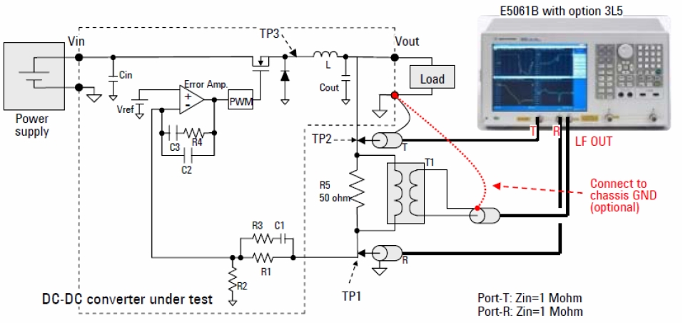
      I use tps54620 for inverting operation with 3.8Vin and -0.9Vout/4A. I apply a 5V on VIN pin. Below is the SCH.The fsw is 950kHz.

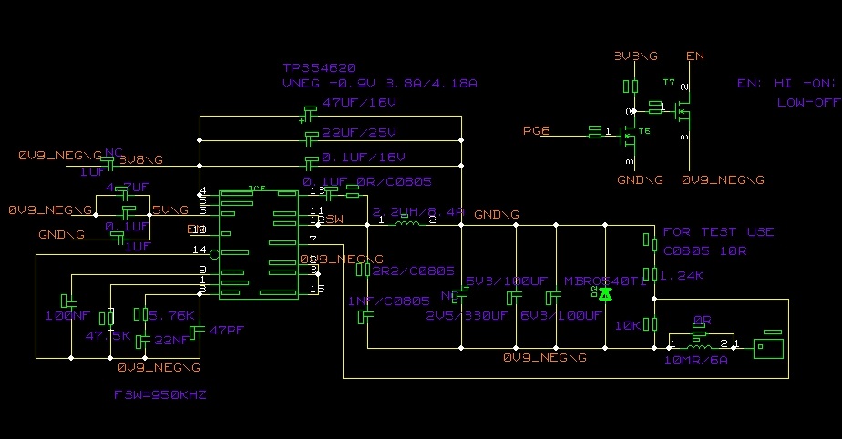
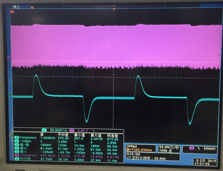
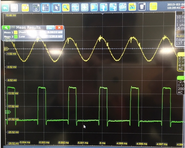
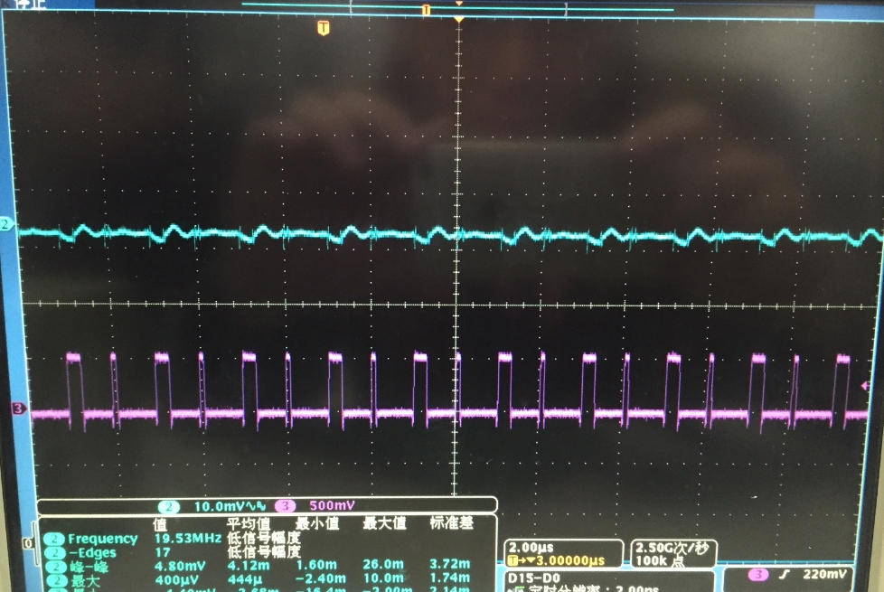
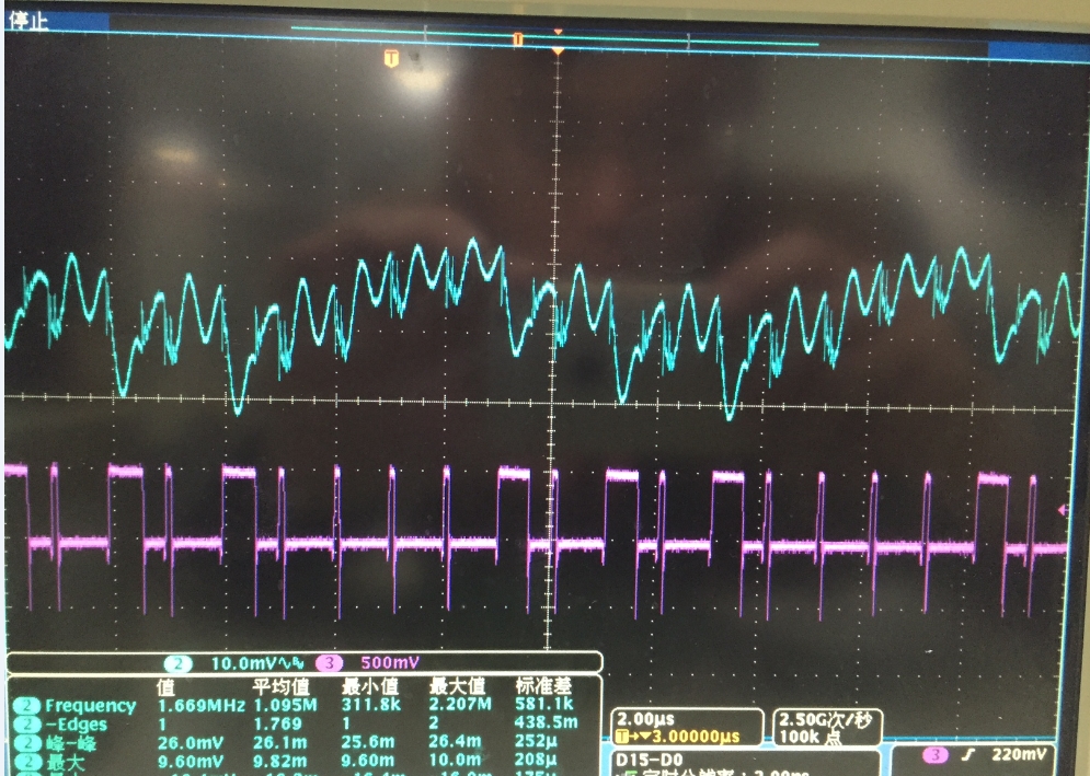
The SW(CH3) and output ripple(CH2) are measured as below shows.The load is from 100mA to 4A. It looks like cycle by cycle current limit is triggered, but no overheating of tps54620 was found. And, the Vout average voltage is always in regulation even @ 4A.

Io=100mA

Io=4A

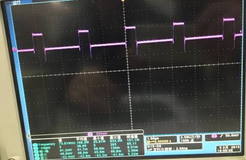
I changed the fsw to 500kHz and Rcomp from 5.76kohm to 800ohm. The fsw looks stable from no load to 2A, but still unstable at 4A.

Could you give suggestion for this?

Thanks

  • You might need a little more capacitance from PVIN to the negative output (IC gnd).  Maybe 10 or 22 uF directly across the IC PVIN and GND pins.  Other wise, I see you are using mixed capacitors on the output.  The compensation values seem normal range, but compensating mixed technology capacitors can be tricky.  Have you measured the loop response or checked it in the time domain by voltage response to load step?

  • Thanks, John.

    I added the PVIN to -0.9V capacitance. And, reduce the fsw to 500kHz, Rcomp to 800ohm, ceramic cap only on the output. It operates stable.

    Transient response 2A to 4A 200mA/us

    Loop

    SW and output ripple

    I would like to minimize the output ripple. However, I found unstable operation happens again in below condition.

    1. fsw >620kHz;

    2. fsw=500kHz, L is increased to 3.3uH, load>3A.

    The operation is the same as before.

    Could you suggest the cause for this?

    Thanks.

  • That output ripple looks pretty low to me if the scale on the left is correct, it is less than 10 mV p-p. Hard to tell as you cropped out the vertical V/div. If you change L and Fsw, then you probably need to re-compensate.
  • Hi John,

    I optimized the ripple as below. How to reduce the pulse I highlighted in yellow?

    Thanks. 

  • Hi John,

    I optimized the ripple as below. How to reduce the pulse I highlighted in yellow?

    Thanks. 

  • It looks like you already have an RC snubber installed, you might check to see if the values are optimum. From the shape of the waveform it may be ESL in the output capacitors or possibly just inductance in your PCB etch. In any case it is very small, it looks like 5mV p-p. You could possibly use an additional LC filter after the output, but reducing ripple much below that may prove difficult with a switching converter
  • Hi John,
    I've a question about how to measure the loop of inverting buck-boost. Below figure is for buck.

    My connection is,

    1. R5 is in the same position toward L,0V and FB pin, taking 0V(GND) as Vout in below figure.

    2. -0.9V(not GND/0V) is the ground for the probes of the tester.

     Hi John,

              I've a question about how to measure the loop of inverting buck-boost.

  • Let me check on it. I may have to order an EVM. If you are in a hurry you can just try it both ways. I don't think you can cause any damage.
  • Thank you, John.
    I will try it after Chinese new year holiday.