This thread has been locked.

If you have a related question, please click the "Ask a related question" button in the top right corner. The newly created question will be automatically linked to this question.

TPS55430 Problem EN ON

Other Parts Discussed in Thread: TPS55340, TPS55340EVM-017

Hello, 


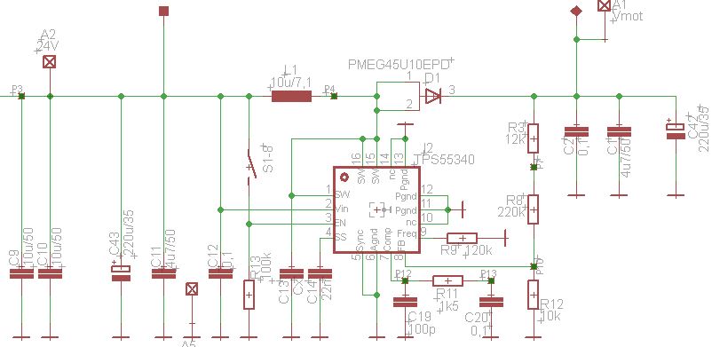
We use the TPS55430 to the voltage for a bipolar stepper motor to increase.

Vin=24V

Vout=30V 3A


S1-8, EN = ON. I switch voltage on it works.

S1-8, EN =OFF. I switch voltage on and later in the active mode I switch the S1-8 EN = ON. Then the TPS55430 is destroyed. Where is the error?


Best Regards

Nils

  • Hi Nils,

    I don't see any issue with the sequence described at the EN pin. Please see some of my thoughts below.

    1. I noticed C13 at the SW pins on the schematic. Is this populated and what is its value?
    2. Could you show some oscilloscope waveforms for the test condition which damages the TPS55340? It would be good to see EN, VIN and VOUT as a starting point. Also if possible take one of the SW voltage at the moment the damage occurs with a small enough time scale to see individual switching pulses.
    3. Any observations on the TPS55340 when it is destroyed, such as pins shorted to ground?
    4. Could you share the PCB layout?

    Best Regards,
    Anthony

  • Hi Anthony,

    1. C13 is not populated

    2. That is dangerous, I have only 2 pieces of TPS55430. Have you a idea, what I could change? Than I try it.

    3. When TPS55430 is destroyd, Pin 1,15,16, 2,3,4 are connected to GND.

    4. This is a 2 Layer Board

    Tank You

    Nils

  • What is the nature of the EN signal you are putting to the EN pin? Does it have a lot of glitches on it because it is a mechanical switch?

    Although it damages the TPS55340, it really is best to measure the waveforms to see if we can spot some unusual stress on the part in this test condition. It's the easiest way to track down the cause of the failure. Alternatively, can you show some of the SW waveforms when you turn the SW on before VIN is applied? We can get an idea of how the circuit is working when it's operating to see if there are any signs of a problem.

    Lastly, looking at the layout the lower FB resistor and FREQ resistor are not placed in the best location. They should be connected to ground near the quite analog ground connected to the AGND pin. Instead they are connected to ground near the noisy power ground at the PGND pin.

  • I have tested evaluation board TPS55340EVM-017. I have R1,R5 changed  in 220k,12k. Vout is 30V. Vin is 24V. Then I switched EN on. The error does not occur immediately, but the 3rd time. The TPS55340 on the evaluation Board is destroyed.

    Another attempt at my circuit. I have changed R3,R8 in 180k,0R. Vout is 24V. Vin is 20V. I have connected C12, C14, C19, C20, R13, R12, R9 to AGND.

    S1-8 is off. I switched S1-8 ON. Here is the oscillogram.

    1-Vin

    2-Vout

    3-EN TPS55340 pin 3

    4-SW TSP55340 pin 1