This thread has been locked.

If you have a related question, please click the "Ask a related question" button in the top right corner. The newly created question will be automatically linked to this question.

UCC28070/restart operation

Other Parts Discussed in Thread: UCC28070

Hi All,

One problem has been occurred on their test board which use UCC28070.
Can you see below and give your advice?

◇Situation
Customers running 5 cycle operation of the AC100V to 40V.
At that time restart of device occurs.
I will attach a waveform of when the problem occurred.
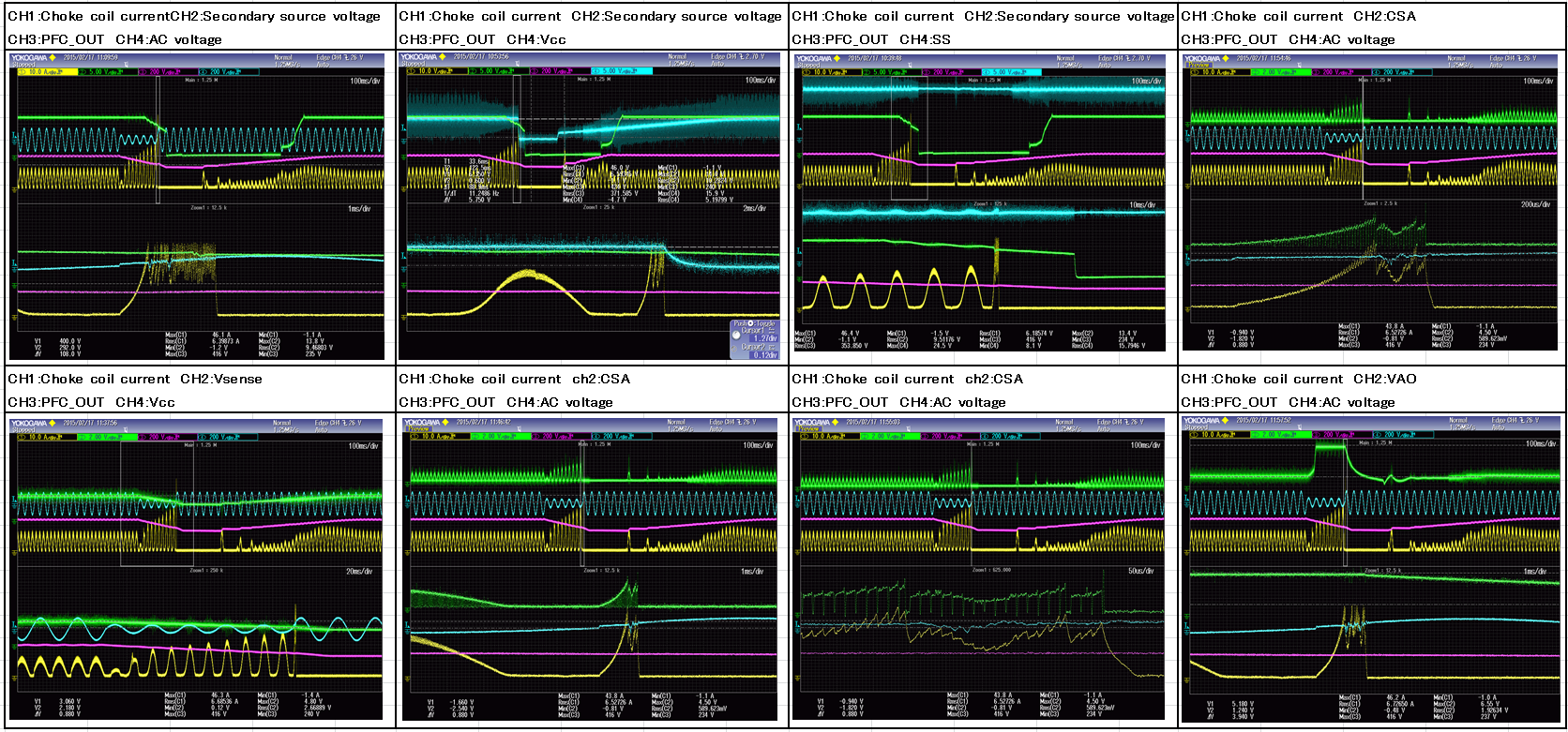


◇Question
Please let me know the possible cause of this behavior.

It is written to be caused at the time of the following condition when I check the data sheet.
· Vcc≦10.2V
· SS≦0.75V
· VAO≦0.9V
· VSENSE≧3.08V or VSENSE≦0.75V
· device temperature≧160 ℃

And to any conditions not also meet is going problem.
Could you tell me why restart occurs.

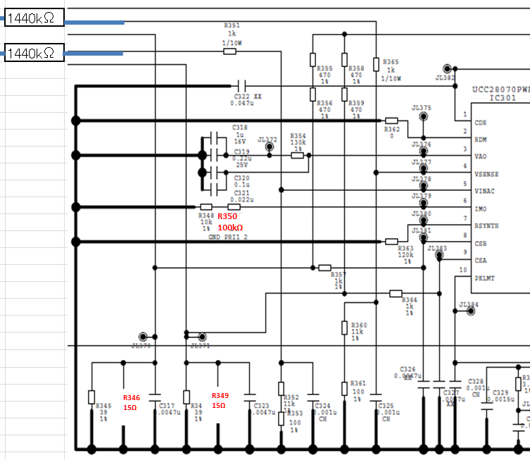
I can share their schematic by off line communication, so please email me directly.
tsukui-y@clv.macnica.co.jp

Best Regards,
Yusuke/Japan Disty

  • You say the device temperature ≧160 ℃

    Do you realize the thermal shutdown threshold is 160 ℃ nominal ?

    Why is it running so hot?

  • Hi ,

    Thank you for your a reply.
    PKG temperature of UCC28070 was 50 ℃.
    Do you have any cause to be considered in the other?

    If you need more information or if I should clarify my comment , please let me know.

    Best Regards,

    Yusuke/Japan Disty

  • There is some confusion here when you say the device temperature is greater than 160C and now you say the package temperature is 50C.
    So let me assume that the device is not hot and offer some more suggestions.......

    The UCC28070 has a DMAX input whereby the maximum duty cycle is programmed and it furthermore has a 95% typical maximum duty cycle in the electrical characteristics table.
    With a 400V output and a 40V input, the DMAX need to be set at >0.9
    Please check what value DMAX is set at.

    Also during an inrush surge event at power-up and AC drop-out recovery, VSENSE<VINAC. In this situation the synthesized inductor current will remain above the IMO reference and the current loop drives the duty cycle to zero. And once VINAC falls below VSENSE the duty cycle increases until steady state operation resumes.
    Does the system recover after the transient?
    Can the pfc stage operate with 40V steady state input ?
  • I spoke to one of my colleagues and he had this suggestion about what was going on:

    "The PFC cannot support the load with 40Vac input.   You can see the inductor current increasing and PFC OUT holds up for a few cycles, then starts to droop.

    The current increases to the point where it hits PKLMT and it suddenly gets all distorted into a noisy hash (because we don’t have slope compensation for the peak limit case).   VCC is NOT turning off, as seen in screen shot 3 (top –row, mislabeled as CH4:SS.. SS is in screenshot 2, mislabeled as CH4:Vcc) so that is not the problem.  

    But as PFC OUT is falling, so is VSENSE.  It is not clear in these photes, but I think VSENSE has a lot of noise on it, and when it falls low enough, the noise from the PKLMT hash is getting in on the VSENSE and tripping the 0.75V/0.60V VSENSE comparator, subsequently tripping the Restart latch.  

    This shuts down the system, until VAO decays to 0.75V a few-100 msec later and the ZeroPower comparator clears the latch, allowing restart."

    Can you please send me a copy of the schematic so that I can check what filtering is used on the VSENSE  input?

  • Hi Jhon,

    Thank you for your support.
    I attached Vsense around circuit.
    Could tell me some advice.


    Best Regards,
    Yusuke/Japan Disty

  • Hi John,

    Thank you for your a support.
    Customer has been improved the problem by changing the layout..

    Best Regards,
    Yusuke/Japan Disty