According to the spec Idd< 10mA and Vdd=15V . We are using Idd= 15mA and Vdd= 14V is there any reliability issue when we use like this?
Please be clear how the Vdd can be 15V when you have internal zener diode of 14V???
This thread has been locked.
If you have a related question, please click the "Ask a related question" button in the top right corner. The newly created question will be automatically linked to this question.
According to the spec Idd< 10mA and Vdd=15V . We are using Idd= 15mA and Vdd= 14V is there any reliability issue when we use like this?
Please be clear how the Vdd can be 15V when you have internal zener diode of 14V???
Hello Tai,
I tried to paste a circuit to show you the answer to your question, but for some reason I can't paste anything into the editor. I hope one day TI will fix their editor so that we can easily paste in drawing to show answers. It would make things a lot better.
Anyway I will try to answer your question using words. The answer to your first question is that the maximum bias current for the UC3808 is 20 mA. So you won't burn up the chip if it is drawing 15 mA. My question to you would be why is the bias current so high? Are driving large MOSFETs straight from the gate drive outputs?. The answer to the second question is the following: the zener in the PWM IC needs a bias resistor to limit the current. This chip is usually used in off-line, high voltage applications from 150 V to 390 V. A 80 to 90 Kohm resistor is placed between the dc bus voltage and the Vdd pin of the PWMIC to limit the current.
I drew a circuit of this but I can't show you on the forum because the "paste from word function" doesn't work for pictures, I guess. I will send it to you directly if you want.
If you are trying to drive the chip with 15 V, place a resistor equal to 1 V/15mA or approximately 68 ohms between the VDD pin and the 15 V source. That will limit the current to 15 mA and keep the PWM IC zener working. Higher voltages require higher value resistance.
Hope this helps,
Chuck
Chuck,
Sorry to hear you were having issues getting content pasted in. For attaching files see this reference guide. For inserting images, our rich text editor won't allow images to be directly copied and pasted in (will need to be local on your drive to then be uploaded).
For inserting images:
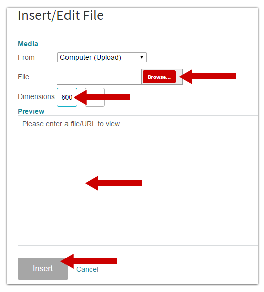
Click on the insert image icon in the rich text editor.
Next: In the pop-up box click on the red "Browse" button to locate the file on your drive. Once selected be sure to input its width pixel dimension (for best display). Once the image is fully uploaded it will appear in the preview pane and at that point click on "Insert." You can also drag and drop images from your drive as described here but this method will allow you to specify the exact width of your image.
Hello Tai,
I looked over your schematic. No, I am pretty sure the 22 Kohms is fine for the RC on pin 4. However I don't understand why you have the PWMIC connected the way you do. I looks to me as though you have the pwm outputs set at a constant maximum. That is the gate voltage is set high throughout the switching period except for the width of the clock pulse. In other words you might be running at greater than 95% duty cycle. I tried working through the logic in the pwmic block diagram. Using the way you have the PWMIC wired as a start, I end up with the output of the T flip flop as being a constant low. Then the nor gates invert the T gate output low to a constant high at the gate output, except for the small time the clock pulse is high. I have never used this chip the way you have it set up, so I could be wrong. Have you measured the gate voltage with an oscilloscope? This could be another reason the chip is getting hot.
Chuck