This thread has been locked.

If you have a related question, please click the "Ask a related question" button in the top right corner. The newly created question will be automatically linked to this question.

UCC27211 peak current question

Other Parts Discussed in Thread: TINA-TI, UCC27211

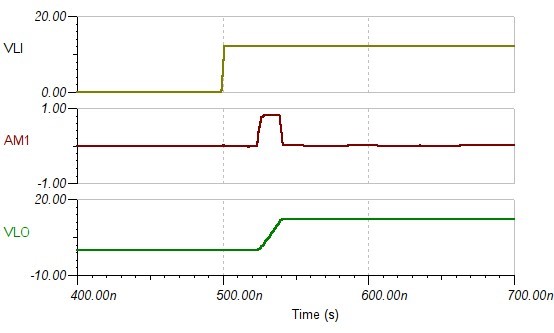
I am perplexed with how to achieve the 4A rated current of the UCC27211 gate driver. I found in practice and then with simulation using TINA-TI that the driver tends to saturate at a lower current. Using TINA-TI I further noticed that the level of saturation current seems to depend somewhat on the capacitance of the load. I don't understand why this would be the case, or how the internals of the UCC27211 could accomplish this. My goal is to get the fastest switching speed possible and this saturation current is limiting. I think that the TINA-TI simulation is without parasitics. I have attempted to attach plots of various load capacitances and a screenshot of the simulation, which was taken directly from the website. Sorry for the different timescales, but I wanted to illustrate that current saturates at low values for low capacitances, thus increasing the switching time if that was a gate capacitance.

 tina ti.zip

  • I've noticed this too...  It's not limiting me yet but I will soon once I solve a few other issues.   Please answer this TI gurus!

  • First, please note that the '4-A Sink, 4-A Source Output Currents' the Features section of the data sheet is not a device specification. Also, the Peak Pull Up Current and Peak Pull Down Currents given in the Electrical Characteristics table are typical values 'Ensured by Design'.

    Now, having said that :- Driver output stages will normally deliver peak current during the time they are making the transition from Hi to Lo and from Lo to Hi rather than when the transition is over and the output is either Hi or Lo. This means that peak current is delivered when the gate of the device being driven is at its threshold voltage. This will drive the device through the Miller region (Plateau) at the maximum possible speed.

    Section 9.2.2.3 in the Data Sheet gives some additional information about how to get the best performance out of the driver -

    In practice, you may actually end up limiting the peak current into the MOSFET in order to meet MOSFET dv/dt or EMI limits.

    Regards
    Colin
  •  This is useful information. I have scoured the datasheet and noticed that information. I also am aware that once I get 4A the design might not be able to handle it. But I'd really like to test at full switching strength, as the switching losses uses a lot of power in our design.  I'm wondering how I can ensure the design to get the maximum currents out of the device and fastest switching times. For example, the datasheet lists the rise time for a 1 nF load as 7.2 ns. I simulated a 1 nF load and I see the current rise to about 800 mA in 4 ns  while the driven capacitor voltage is about 2 V. The current then just stays at 800 mA until the capacitor is charged. Clearly if this was a gate drive capacitance, it wouldn't be turned on and it would only be driven across the miller plateau at 800 mA instead of 4A. This design is only in simulation so I don't see what else I could do to get more current out of it.

    Do you recommend a different part for high speed switching?

  • Hello Lee

    TI does offer a range of drivers but I wouldn't recommend choosing a different device just yet.

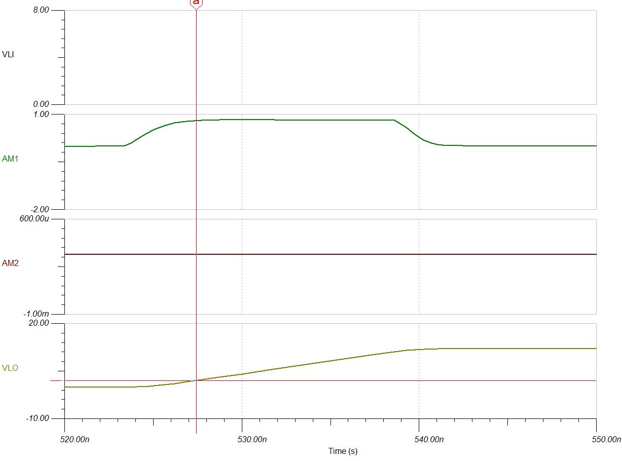
    I think the problem is that the TI model doesn't really reflect the true device performance very well. For example, I downloaded the UCC27211 TINA-TI Transient Reference Design schematic from the website and had it drive a IRF630 MOSFET. The model displays no miller effects and the output current (AM1) continues to flow even when the gate has already reached 12V - cursor

    Anyhow, I would suggest that you get hold of some actual drivers and see how they perform on the bench. They are used in the evaluation module atwww.ti.com/.../ucd3138hsfbevm-029   but this   but this

     but this isn't cheap. The alternative would be to make up a small test bed of  your own.

    BTW, the best way to measure gate currents is to put a small resistor in the gate circuit and use a differential probe (or subtract two 'scope channels'. 'small' could be anything from 100mOhms to 10 Ohms - just as long as it doesn't reduce the current being measured.

    Regards
    Colin