This thread has been locked.

If you have a related question, please click the "Ask a related question" button in the top right corner. The newly created question will be automatically linked to this question.

TPS2384 Question

Other Parts Discussed in Thread: TPS2384

Hi. My name is taehwan lee. i am hw engineer worked in Pinetorn., co. ltd in Republic of Korea.

I have one question about TPS2384.

We product HD4K & HD3K NVR.

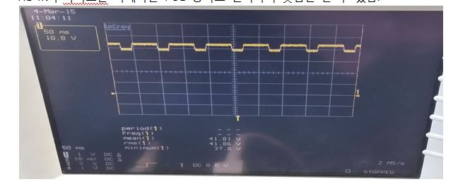
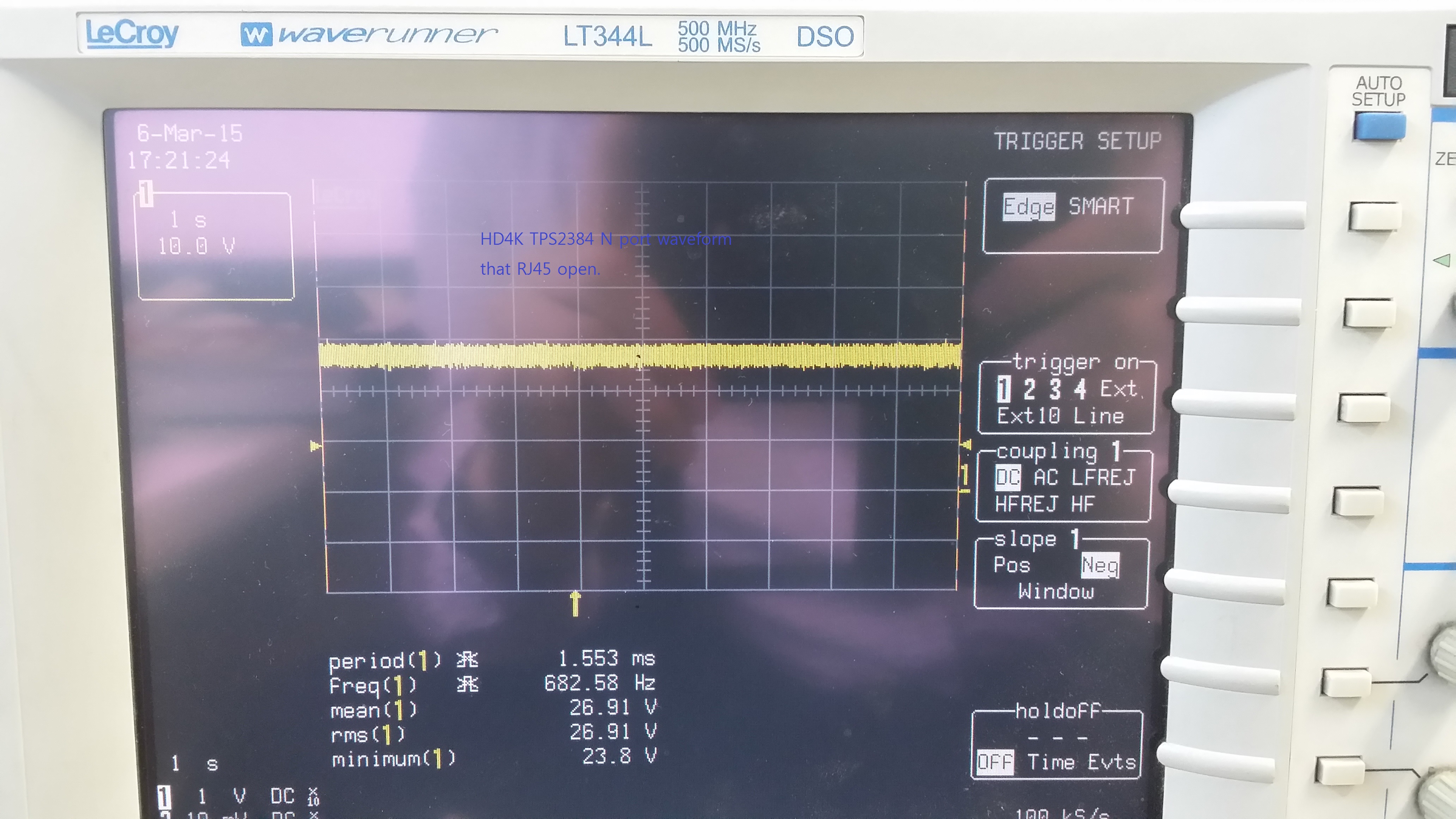
Recently, one of POE camera using CAT-5E connect to HD4K. But does not operated. Because TPS2384 in HD4K  does not recognize POE device.

show below TPS2384 waveform... "... but the other POE camera operated well in HD4K.

and POE camera (dont worked in HD4K) operated well if connected to POE Hub.

if you have a solution or good idea, please advise to me.

ps> attach HD4K circuit...HD4K.pdf

also attach HD3K circuit HD3K.pdf

  • According to the plot, TPS2384 measured an invalid detection resistor from the PD. Does this PD work on other TPS2384 ports or fail on all of them? One PD test is to apply voltage to the power port between ~4V and 9V and measure the current using a uMeter. You can use  simple DC power supply with DMM in between with a modified ethernet cable. The V/I should be around 25kohm. TPS2384 will fail below ~16kohm and above ~30kohm. The PD should be between ~23k and 26.5kohm.

  • we have two application HD3K, HD4K using TPS2384.

    IN HD3K, PD works well.

    TPS2384 circuit in HD3K & HD4K is not same. so I try to tps2384 circuit in HD4K modify ..
    like tps2384 circuit in HD3k .. but result is FAIL...

    and i do other test... IN HD4K, using i2c bus, I reset TPS2384 ..then PD work ..
    but reset control is not answer that i want.

    TPS2384 in HD3K, HD4K is auto mode. but in HD4K , i can access TPS2384 using I2C Bus.

    if you need more information... please reply ^^

  • In the HD4K, can you check the discovery status bit (see Table 8 in the DS) for the failing port(s)? Do all 4 ports fail or just one or two? You can also run some tests by making the port circuit changes on HD4K match the working HD3K (any hardware changes that might have caused detection to fail).
    If the product can be placed in PMM (MS pin = 1), then other tests using I2C can be run in order to measure what the TPS2384 thinks the detection resistor value is (using Discovery 1 and 2 commands).
  • the discovery status bit value is "1(discovery fail)". all 4 ports are same.

    and i have a question about AC disconnect ..

    what is AC disconnect ? We use AC disconnect circuit in HD3K.

    is AC disconnect improve funciton to detect PD device ??
  • and I attach "TPS2384 circuit in HD4K"

    would you check circuit if it has problem or not?
  • today I upload HD3K circuit(PDF) and 2 waveform.

    In the HD4K, N port of TPS2384 wavefrom does not change(always about 27V)
    but HD3K, N port waveform does not. why???
  • I cannot find anything wrong with HD4K schematic, however I cannot see where the Px+/Nx- signals go. It could be that connection is causing the issue. The HD4K waveform indicates that the port is not even searching (searching is the periodic open circuit probe waveform you show in HD3K). You mentioned that applying a soft reset will clear the condition, right? When you do this, does the HD4K searching waveform come back?

    In HD4K, you apply the PORB signal through the opto. It is possible that the reset timing causes TPS2384 to power up with ports disabled. Also in HD4K, the PSE_3.3V is used or pullups. This can only power ~2-3mA so check the DCV of that node to ensure that V3.3 is not overloaded.

  • I try to soft reset TPS2384 in HD4K, but waveform did not changed.

    I remove C26(0.22uF between P and N pin) In HD4K, then I can see similar waveform(voltage level 0v~27v) to HD3K.

    is there important artwork guides for using TPS2384??

    i can't understand why disappear "searching waveform" if I attach 0.22uF between P and N pin.

    IN attached HD4K circuit, P1 and N1 PIN of TPS2384(PIN6 & Pin7) connect F20 and F21(Ferrite Bead) of 2Page.. you find that easily..

    please check the rest of circuit.

    For using TPS2384, the more i learn about tps2384, the more I have questions...
  • You seem to be on a path to solving the issue. This is the type of comparative troubleshooting method which is required to solve a problem like this. Having a working system to compare with is valuable. By the way, I noticed that the 0.22uF capacitor was only rated for 50V. Please try using a 100V rated ceramic capacitor (X7R dielectric preferred).
  • i have a question if N1 pin is completely open, what waveform I can see ???
  • Please see the attached TPS2384 port open circuit waveforms taken on TPS2384EVM-109.

    N pin without port capacitor: ALTA and ALTB mode

    N pin with port capacitor: ALTA and ALTB modeTPS2384_OC_WAVES.zip

  • I solved problem. ALTA/B pin of TPS2384 in HD3K pdf circuit shows "LOW". But.. in HD3K pcb, the value is "HIGH".

    Thank you for your advise.